
Wheel action force detector for detecting axle forces absent brake torque

a technology of action force detector and axle force, which is applied in the direction of force/torque/work measurement apparatus, electric control, instruments, etc., can solve the problems of insufficient precision control of slip ratio, inability to obtain minimum braking distance, and inability to maximal braking force, so as to achieve easy measurement, reduce acceleration distance, and reduce braking distance

Inactive Publication Date: 2004-11-11
JAPAN ELECTRONICS IND LTD
View PDF3 Cites 6 Cited by
  • Summary
  • Abstract
  • Description
  • Claims
  • Application Information

AI Technical Summary

Benefits of technology

[0010] In this device, the stress generated in the axle by the wheel action force is detected by the stress detection sensor installed through the spacer means. The stress is proportional to the wheel action force and, therefore, said stress detection sensor detects the wheel action force through the stress. Since the stress detection sensor is embedded in the axle, interferences to the sensor output signal from wheel action forces other than the target wheel action force can be decreased and, moreover, the sensor can be protected against the external environment. Furthermore, since the detection signal from the stress detection sensor is processed by the signal processing circuit, interferences from wheel action forces other than the specific wheel action force subjected to measurement can be further decreased.
[0028] In accordance with the present invention, the technology for measuring stresses, loads or the like with a stress detection sensor equipped with strain gauges as embedded in an optional structure offers the effect that, by positioning the stress detection sensor in a suitable orientation in a hole, any desired stress, load or the like can be measured. Moreover, by placing a plurality of stress detection sensors in suitable positions and orientations, overlapping stresses or loads can be eliminated or decreased and the necessary stress or load be extracted and measured. Furthermore, this stress measuring device has an additional advantage that the stresses generated internally in an object structure can be easily measured.

Problems solved by technology

Therefore, in the above-mentioned system, the braking force may not be maximal depending on road surface condition and the minimum braking distance cannot be obtained in such cases.
Furthermore, since the chassis speed is estimated from the wheel speed, control of the slip ratio is deficient in precision.
However, in this system, the tire torque is indirectly determined by arithmetic operation from the wheel angular acceleration and bake fluid pressure but because of indefinite constants such as the wheel inertia efficiency and the braking efficiency of the brake, the precision of calculated values is not sufficiently high.
In this case, too, there is the same problem as in the ABS wherein control is based on the wheel speed.

Method used


Image

  • Wheel action force detector for detecting axle forces absent brake torque
  • Wheel action force detector for detecting axle forces absent brake torque
  • Wheel action force detector for detecting axle forces absent brake torque

Examples


Embodiment Construction

[0050] The following are preferred embodiments of the invention and should by no means be construed as limiting the scope of the invention as defined in the claims.

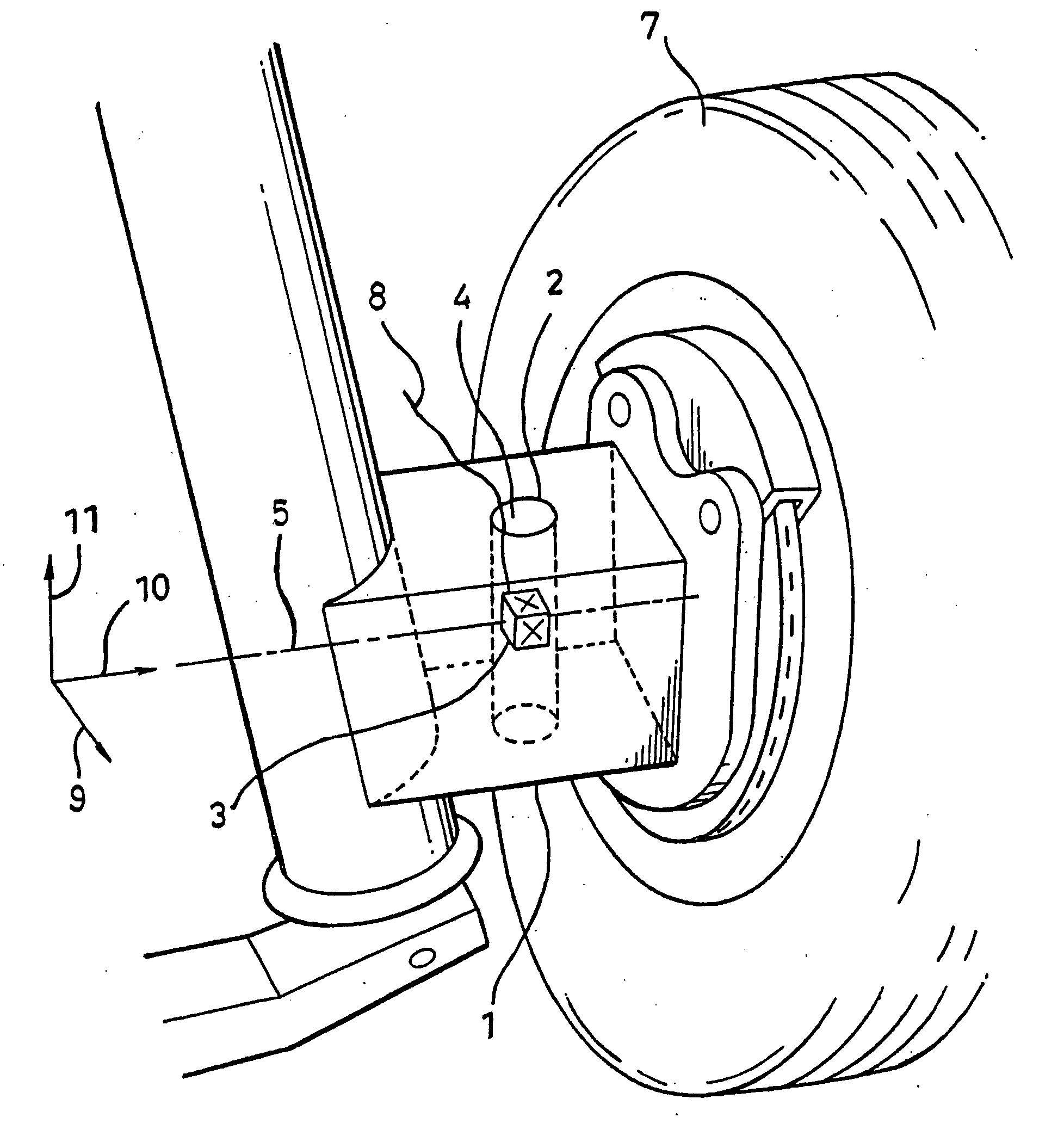
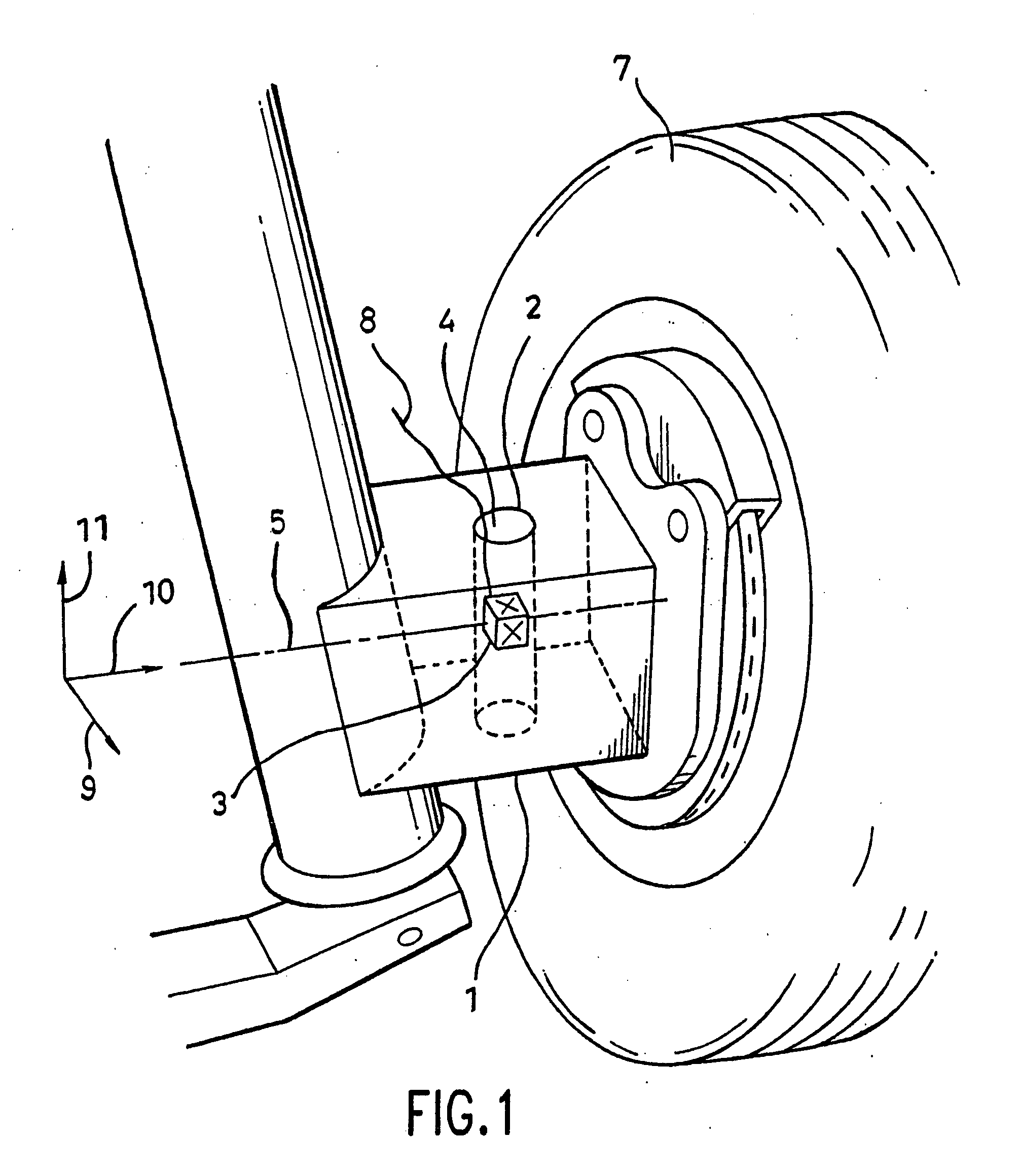
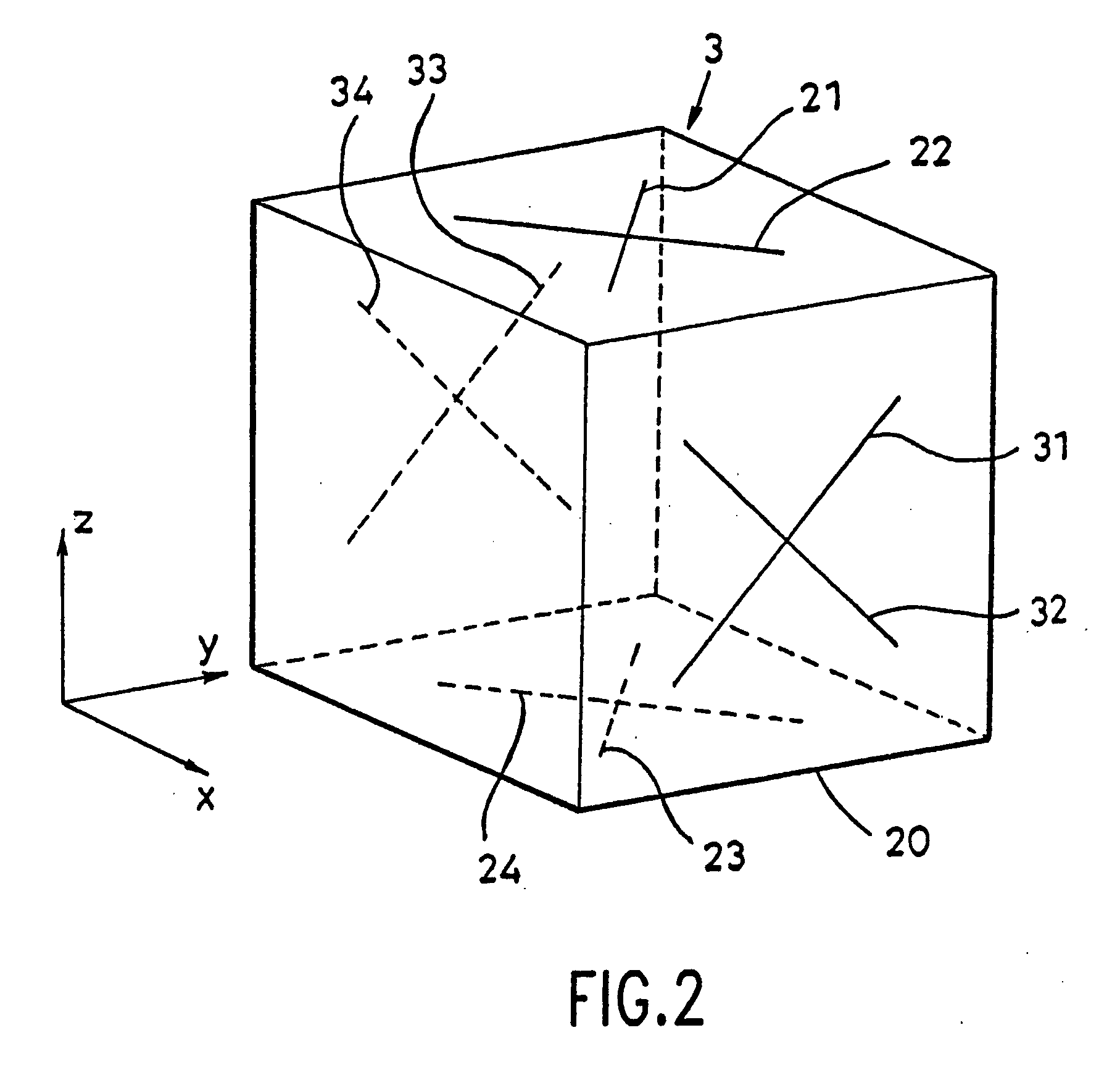
[0051] Specific examples of the device for measuring action force of a wheel for measuring the road surface friction coefficient are shown in FIGS. 1, 2 and 3. FIG. 1 shows the installation state of a stress detection sensor. FIG. 2 shows a stress detection sensor and FIG. 3 shows a signal processing circuit. As an example, there is shown the case in which the stress detection sensor is mounted in the axle of a driven wheel of a car having the strut type suspension structure which is often used in automobiles. From the top to the bottom of an axle (a knuckle in this example), a hole 2 is formed along a direction 11 perpendicular to the road surface and intersecting the centerline (stress neutral line) of the axle. The diameter of the hole 2 may for example be about 5 mm to about 10 mm. Here, the axle centerline (stress ne...


PUM

PropertyMeasurementUnit
road surface friction coefficientaaaaaaaaaa

Abstract

A device for measuring action force of a wheel includes a vehicle axle upon which the wheel is mounted, the vehicle axle having a stress neutral line, and a stress detecting sensor having at least one strain gauge. The stress detecting sensor is disposed within the vehicle axle so as to detect at least one of a horizontal shear stress and a vertical sheer stress with the at least one strain gauge being one of aligned with or proximate the stress neutral line thereby permitting substantial removal of axle torque influence from an output of the stress detecting sensor. A signal processing circuit processes the output of the stress detecting sensor.

Description

[0001] 1. Technical Field[0002] The present invention relates to a device for measuring action force of a wheel for detecting road surface frictional force, vertical drag, road surface friction coefficient, etc. which can be a constituent element of a brake system with skid control for preventing lock (seizure) of the wheels of a vehicle on sudden stops or a traction control system for preventing excessive slip of the wheels at acceleration, and a device for measuring stress of a structure for measuring stresses produced in optional structures.[0003] 2. Prior Art[0004] The antilock brake system (ABS) of the conventional vehicle such as an automobile generally employs the principle of controlling the brake action automatically according to the chassis speed and wheel speed in such a manner that the slip ratio will fall with a certain range [cf. Japanese Patent Publication No. 59-30585 and Japanese Kokai Patent Publication No. 60-61354). The relationship between road surface friction ...

Claims


Application Information

Patent Timeline
Patent Type & Authority Applications(United States)
IPC IPC(8): B60G17/019B60T8/171B60T8/172B60T8/52B60T17/22F02D35/00F02D41/22F16D55/00F16D66/00G01L5/00G01L5/16G01L5/20
CPCB60G17/019B60G2204/115B60G2400/64B60G2401/122B60G2800/22B60G2800/92B60T8/171B60T8/172B60T8/1725B60T8/52B60T17/22B60T2210/12B60T2240/02F02D35/0007F02D35/0053F02D35/0092F02D41/221F16D66/00F16D2055/0008F16D2066/005G01L5/0004G01L5/161G01L5/20Y02T10/40G01L5/1627
Inventor MIYAZAKI, NAGAO
Owner JAPAN ELECTRONICS IND LTD
Learn More