Configurable circuit and method for detecting the state of a switch

a technology of configurable circuits and switches, applied in the direction of contacts, electric digital data processing, instruments, etc., can solve the problems of large power consumption, ineffective or reliable implementation of security systems, and bulky existing security systems

Active Publication Date: 2004-11-11
STMICROELECTRONICS SRL
View PDF3 Cites 2 Cited by
  • Summary
  • Abstract
  • Description
  • Claims
  • Application Information

AI Technical Summary

Benefits of technology

0005] Exemplary embodiments of the present invention overcome the above-described shortcomings in existing tamper detection circuits and satisfy a significant need for a detection circuit that may accommodate any of a number of different applications. According to an exemplary embodiment of the present invention, a detection circuit may be configured into any of a number of different switch detection configurations. For example, the detection circuit may be configured to be in a normally-closed-tamper-to-high configuration, a normally-closed-tamper-to-low configuration, a normally-open-tamper-to-hi-gh configuration and a normally-open-tamper-to-low configuration.

Problems solved by technology

In many instances, such security systems are not implemented in an efficient or reliable manner.
Some existing security systems are bulky and consume a relatively sizeable amount of power.
Further, circuitry of the security system are relatively rigid and are not adaptable to different security system applications.

Method used


Image

  • Configurable circuit and method for detecting the state of a switch
  • Configurable circuit and method for detecting the state of a switch
  • Configurable circuit and method for detecting the state of a switch

Examples


Embodiment Construction

[0016] The present invention will now be described more fully hereinafter with reference to the accompanying drawings in which exemplary embodiments of the invention are shown. This invention may, however, be embodied in many different forms and should not be construed as being limited to the embodiments set forth herein. Rather, the embodiments are provided so that this disclosure will be thorough and complete, and will fully convey the scope of the invention to those skilled in the art.

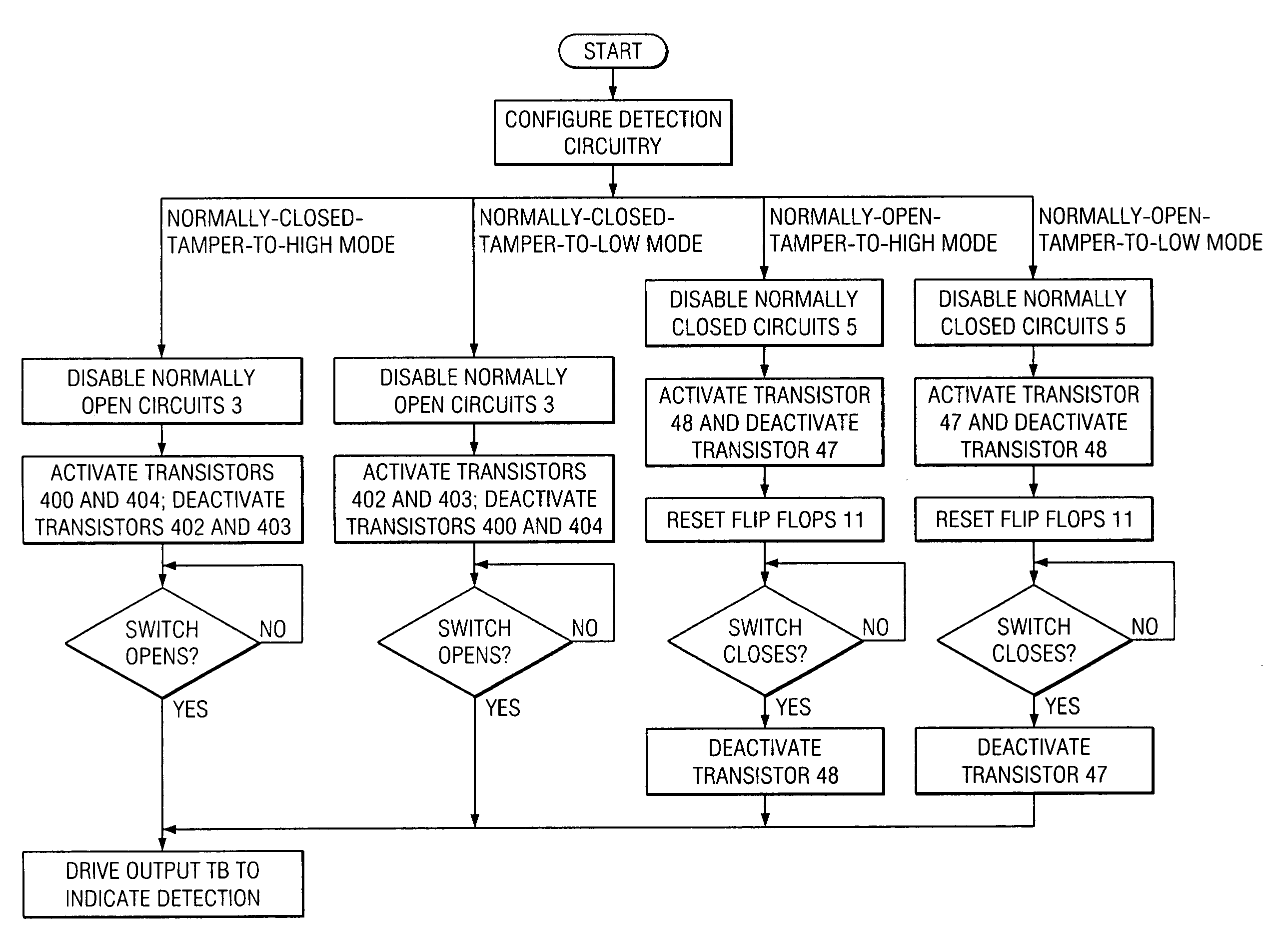
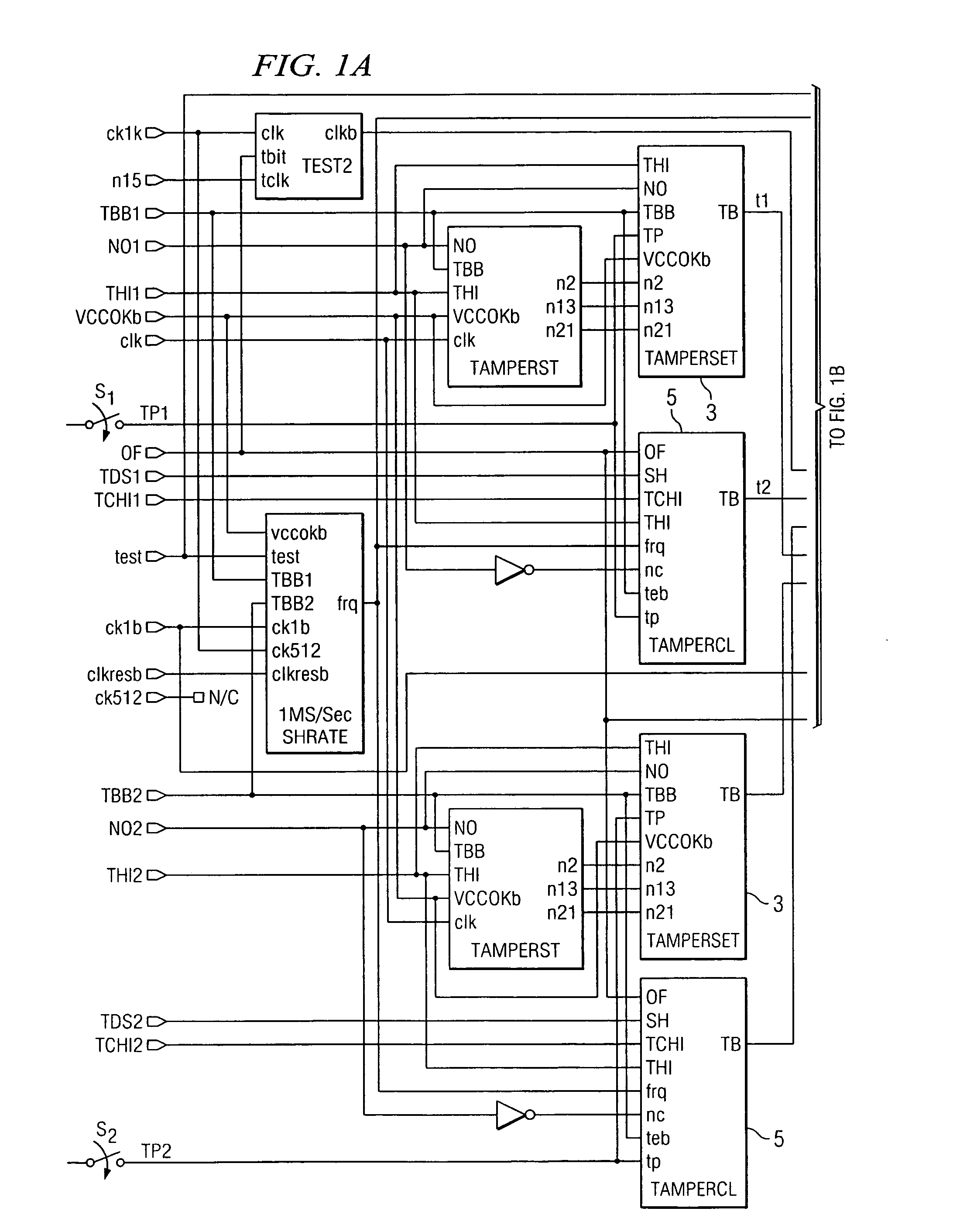
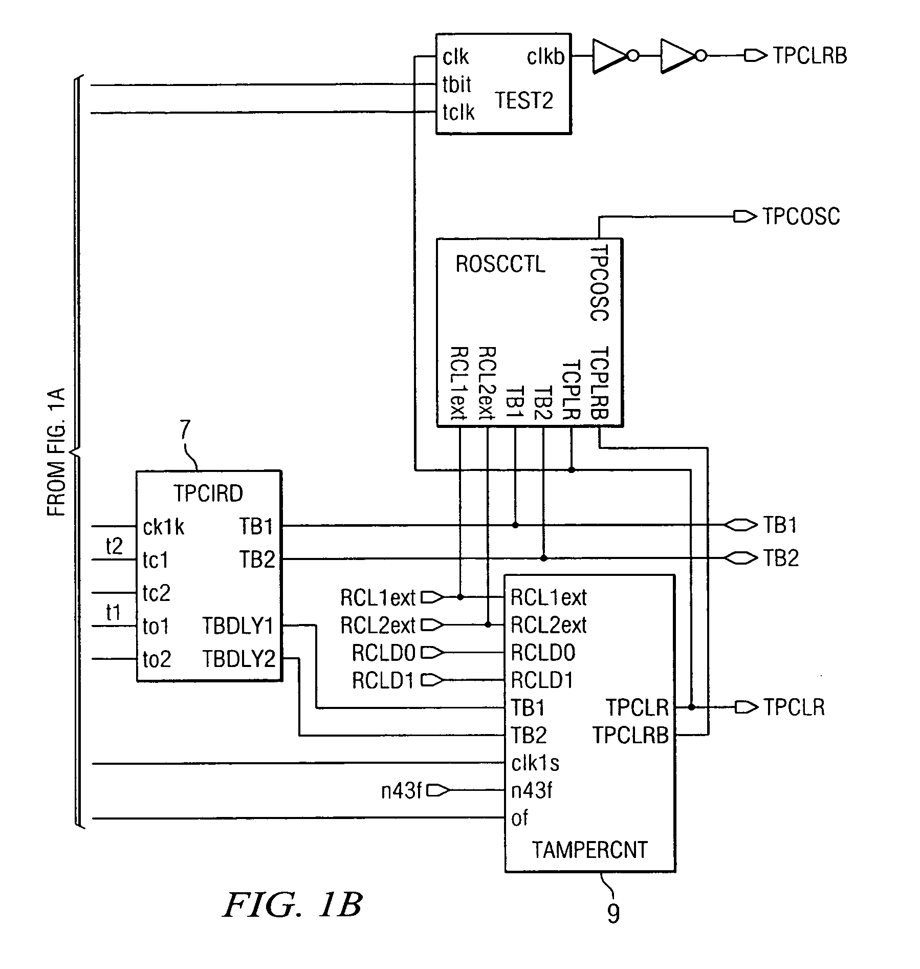
[0017] Embodiments of the invention may include detection circuitry 1 for monitoring one or more switches. The exemplary embodiment of the present invention described hereinbelow is a circuit for monitoring the state of two switches. The circuitry for monitoring one switch may be the same as the circuitry for monitoring the other switch.

[0018] The detection circuitry 1 may include circuitry for selecting one of the detection configurations. When a configuration is selected, circuitry dedicated to th...


PUM


Abstract

A circuit and method are disclosed for monitoring the state of at least one switch. The circuit may include a first circuit, coupled to a switch, for detecting whether the switch is in one of a closed state and an open state and generating a signal having a value based upon the detection. The circuit may further include a second circuit, coupled to the first circuit, for configuring the first circuit to selectively detect the switch switching from a normally open state and to selectively detect the switch switching from a normally closed state.

Description

[0001] The present application claims priority from U.S. Provisional Application No. 60 / 469,325, filed May 9, 2003, the disclosure of which is hereby incorporated by reference.[0002] The present application is related to U.S. patent application Ser. No. 10 / 147,639, filed May 17, 2002, which is incorporated by reference herein in its entirety.[0003] Techniques exist for monitoring the configuration of mechanical devices and detecting whether the mechanical devices have been tampered with or otherwise physically changed. For instance, existing security systems are known to electronically monitor the state of mechanical or magnetic switches disposed about a building or attached to a lockable storage container in order to determine whether such switches change from an open state to a closed state or vice versa in response to the building or container being tampered with. In many instances, such security systems are not implemented in an efficient or reliable manner. Some existing securi...

Claims


Application Information

Patent Timeline
Patent Type & Authority Applications(United States)
IPC IPC(8): H01H9/16
CPCH01H9/167
Inventor YIN, RONG
Owner STMICROELECTRONICS SRL
Why Eureka
Try Eureka