

Apparatus and methods for drilling a wellbore using casing
Inactive Publication Date: 2004-12-09
WEATHERFORD TECH HLDG LLC
View PDF99 Cites 165 Cited by
- Summary
- Abstract
- Description
- Claims
- Application Information
AI Technical Summary
Problems solved by technology
When forming a subsea wellbore, the length of wellbore that has been drilled with a drill string is subject to potential collapse because of the soft formations present at the ocean floor.
Also, sections of the wellbore intersecting regions of high pressure can cause damage to the drilled wellbore during the time lapse between the formation of the wellbore and the lining of the wellbore.
Additional cost and time for completing a wellbore are inherent results of the current drilling with casing operation because the motor system must be retrieved from the wellbore prior to the cementing operation.
Each drilling platform represents a relatively significant cost.
Also, governmental regulations allow only a limited number of platforms over a given surface area of the body of water.
A common problem with drilling subsea wellbores is encountered due to the attempt to maximize hydrocarbon production by maximizing the number of wellbores drilled from slots in a platform of limited surface area.
Unfortunately, drilling the wellbores through the slots which are so close to one another leaves little room for even small directional deviations when the wellbore is not drilled directly downward into the subsea formation.
Sometimes, the wellbores are accidentally deflected and drilled into one another, causing the wellbores to intersect.
Thus, the allowed drilling area from the platform is reduced, causing a decrease in the production of hydrocarbons from the subsea formation.
This method fails to prevent caving in of the wellbore between the time in which the hole is drilled and the time in which the casing is inserted into the wellbore.
Moreover, the increased time and expense inherent in running the drill string and the casing string into the wellbore separately are disadvantages of this method.
This method involves at least two run-ins of the drill string to drill two holes of different diameter, increasing time, expense, and wellbore collapse potential.
Additionally, with the current drilling systems, drilling tools and casing strings need to be run and / or retrieved a plurality of times into and / or out of the wellbore to complete drilling, casing, casing expansion, and cementing operations, resulting in substantial costs and length of time for completing a well.
As an example, one disadvantage arises due to a lack of proper support between the casing latch 3106 and the point of contact of the pilot bit 3108.
This leaning is difficult to control and can severely affect the intended curvature and trajectory of the deviated hole.
Further, without proper support, excessive lateral and axial vibrations in the BHA 3100 may reduce removal rate, reduce operating lifetime, and / or cause damage to the various components of the BHA 3110, particularly when drilling in rotary mode.
A further disadvantage of the system of FIG. 32 lies in the large length of the rat hole drilled below the lower end of the casing 3104, into which the casing 3104 must be lowered over the BHA 3100.
Additionally, the system places unnecessary directional force directly on the BHA 3100.
Still another disadvantage in conventional drilling with casing systems is that the MWD 3109 does not provide real time survey information and, thus, the trajectory of the deviated hole can only be verified after drilling.
However, where the drill string is later used as the casing, this is not practicable because the orientation tool is expensive, and therefore it is undesirable to abandon it in the well.
Also, the survey tool, if left in the well, would create an obstruction to well fluid recovery, or for the passage of an additional drilling element therepast and thence through the end of the casing to continue drilling the borehole to greater extent, and thus would need to be drilled or milled out of the bore hole.
Method used
View moreImage
Smart ImageViewing Examples

Examples
third embodiment
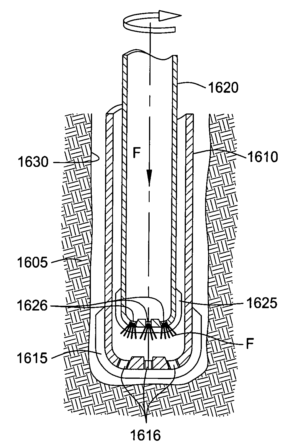
[0068] FIG. 27 is a section view of a nozzle assembly disposed in a tool body.
Login to View More PUM
 Abstract
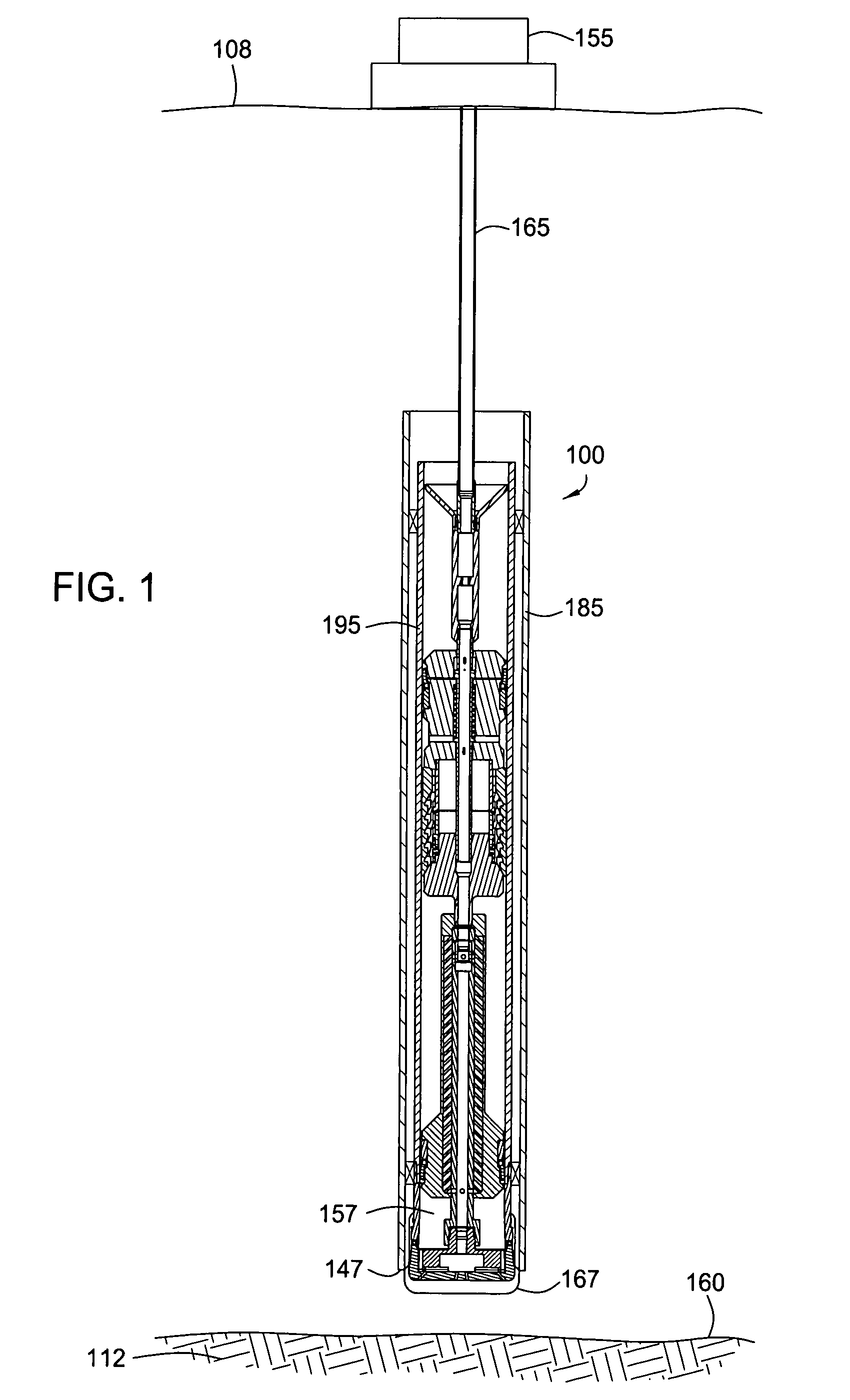
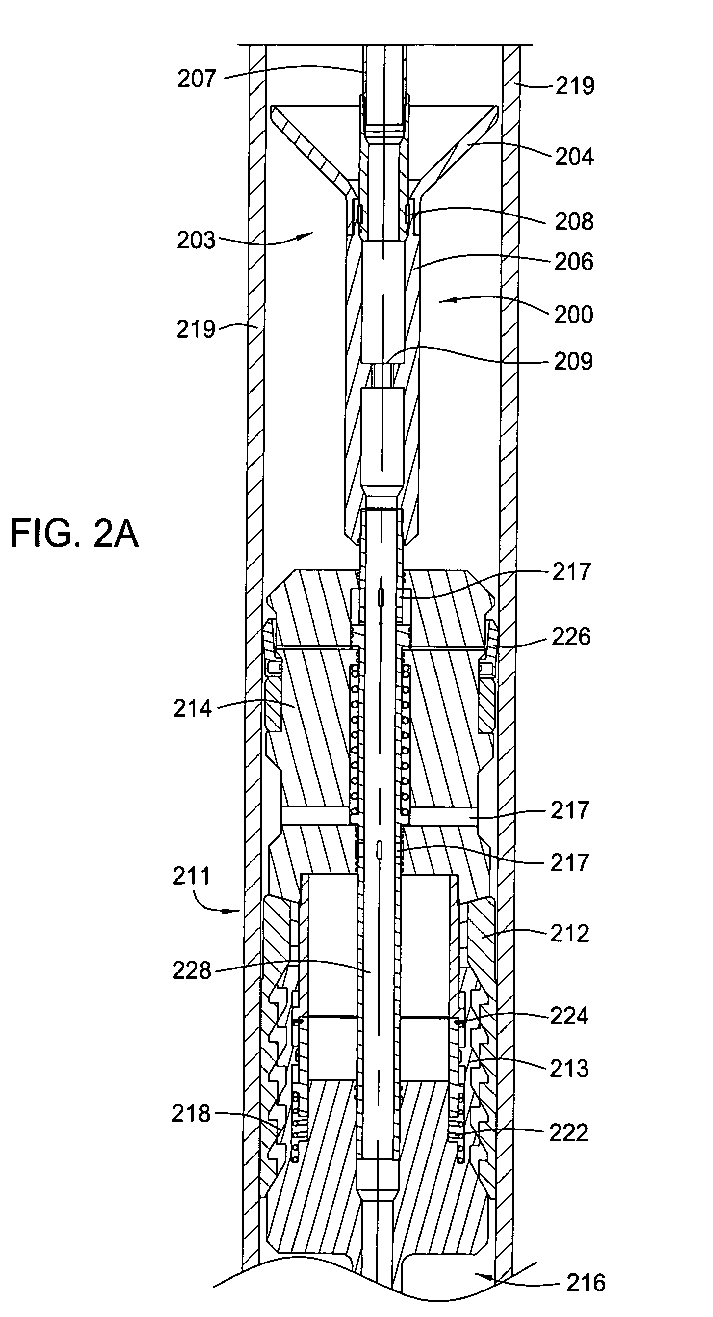
Apparatus and methods for drilling with casing. In an embodiment, methods and apparatus for deflecting casing using a diverter apparatus are disclosed. In another embodiment, the apparatus comprises a motor operating system disposed in a motor system housing, a shaft operatively connected to the motor operating system, the shaft having a passageway, and a divert assembly disposed to direct fluid flow selectively to the motor operating system and the passageway in the shaft. In another aspect, methods and apparatus for directionally drilling a casing into the formation are disclosed. Methods and apparatus for measuring the trajectory of a wellbore while directionally drilling a casing into the formation are also described.
Description
[0001] This application is a continuation-in-part of U.S. patent application Ser. No. 10 / 257,662 filed on Apr. 2, 2001, which application is herein incorporated by reference in its entirety. U.S. patent application Ser. No. 10 / 257,662 is the national phase application of PCT / GB01 / 01506 filed on Apr. 2, 2001.[0002] This application claims benefit of U.S. Provisional Patent Application Ser. No. 60 / 444,088 filed on Jan. 31, 2003, which application is herein incorporated by reference in its entirety. This application further claims benefit of U.S. Provisional Patent Application Ser. No. 60 / 452,202 filed on Mar. 5, 2003, which application is herein incorporated by reference in its entirety. This application further claims benefit of U.S. Provisional Patent Application Ser. No. 60 / 452,186 filed on Mar. 5, 2003, which application is herein incorporated by reference in its entirety. This application further claims benefit of U.S. Provisional Patent Application Ser. No. 60 / 452,317 filed on M...
Claims
Login to View More Application Information
Patent Timeline
 IPC IPC(8): B05B1/00E21B7/06E21B7/18E21B7/20E21B10/60E21B10/61E21B21/10E21B33/14E21B34/00E21B41/00E21B47/01
CPCB05B1/00E21B7/06E21B7/065E21B7/18E21B7/208E21B10/61E21B17/14E21B21/103E21B33/14E21B41/0078E21B47/01E21B2034/002E21B43/105B05B1/002E21B2200/04
InventorGIROUX, RICHARD L.GALLOWAY, GREGORY G.LE, TUONG THANHJACKSON, RAYMOND H.NAZZAL, GREGORY R.SWARR, JAMES C.BRUNNERT, DAVID J.BEASLEY, WILLIAM M.LIRETTE, BRENT J.ODELL, ALBERT C.TERRY, JIMMCKAY, DAVEALKHATIB, SAMIRWARDLEY, MIKE
OwnerWEATHERFORD TECH HLDG LLC