Gear wrench allowing easy force application

a technology of gear wrenches and force plates, applied in the direction of wrenches, screwdrivers, manufacturing tools, etc., can solve the problems of design failure to meet ergonomics, ineffective force components of vertical components, accidents and occupational hazards, etc., and achieve the effect of convenient force application, easy force application, and convenient force application

Inactive Publication Date: 2004-12-16
DANAHER TOOL
View PDF13 Cites 0 Cited by
  • Summary
  • Abstract
  • Description
  • Claims
  • Application Information

AI Technical Summary

Benefits of technology

0014] FIG. 3 illustrates an alternative embodiment of the gear wrench allowing easy force application according to this invention.
0015] FIG. 4 illustrates a further embodiment of the gear wrench allowing...

Problems solved by technology

However, such a design fails to meet ergonomics because the operator's hand would need to incline for a certain degree along with the inclined tail.
However, the vertical component of force Fh is an ineffective component of force and ...

Method used


Image

  • Gear wrench allowing easy force application
  • Gear wrench allowing easy force application
  • Gear wrench allowing easy force application

Examples


Embodiment Construction

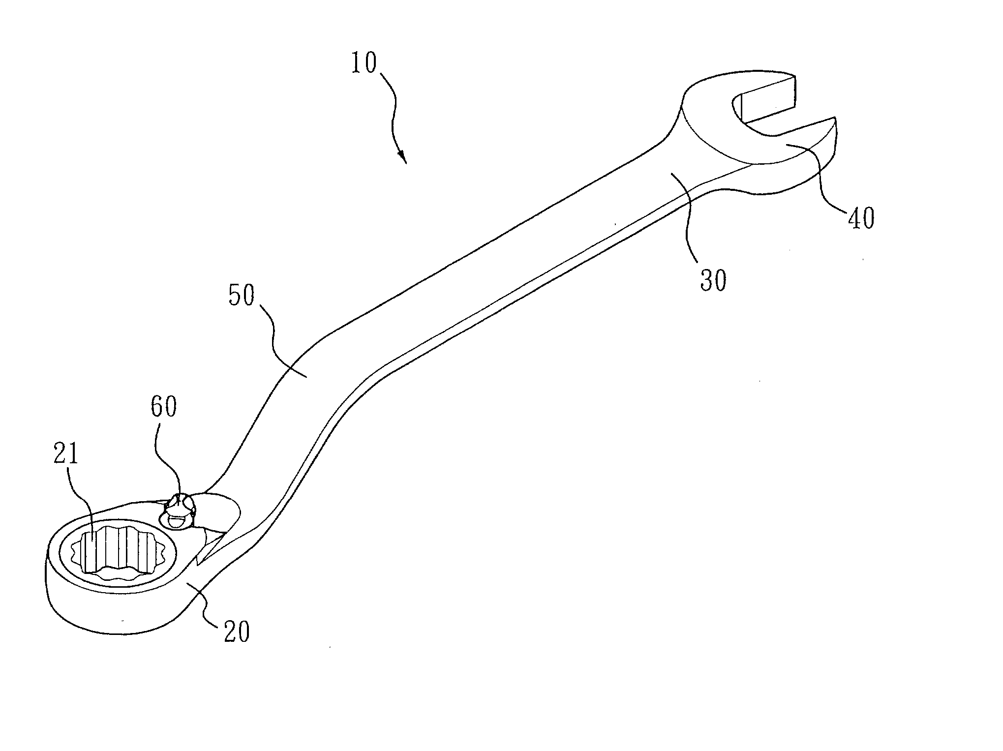
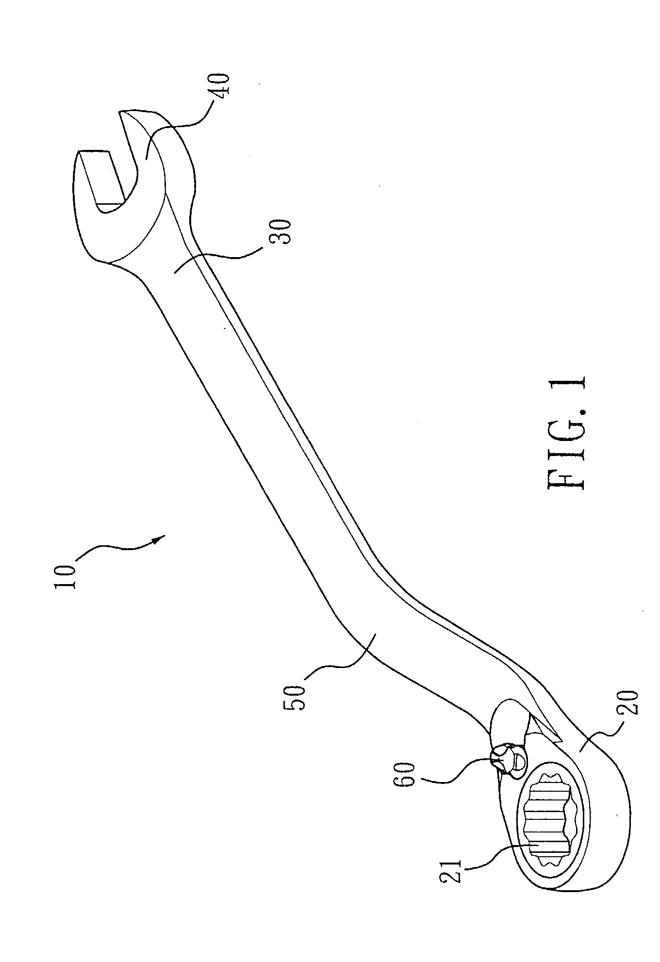
[0019] FIG. 1 illustrates a perspective view of a gear wrench 10 allowing easy force application according to this invention.

[0020] With reference to FIG. 1, the gear wrench 10 according to this invention includes: a head 20, a tail 30, a neck 50 formed with the head 20 and the tail 30, and an open wrenching end 40 provided to the tail 30 at an end of the gear wrench 10 opposing the head 20.

[0021] The head is formed with a receiving compartment thereon for receiving a gear ring 21 to form a box end.

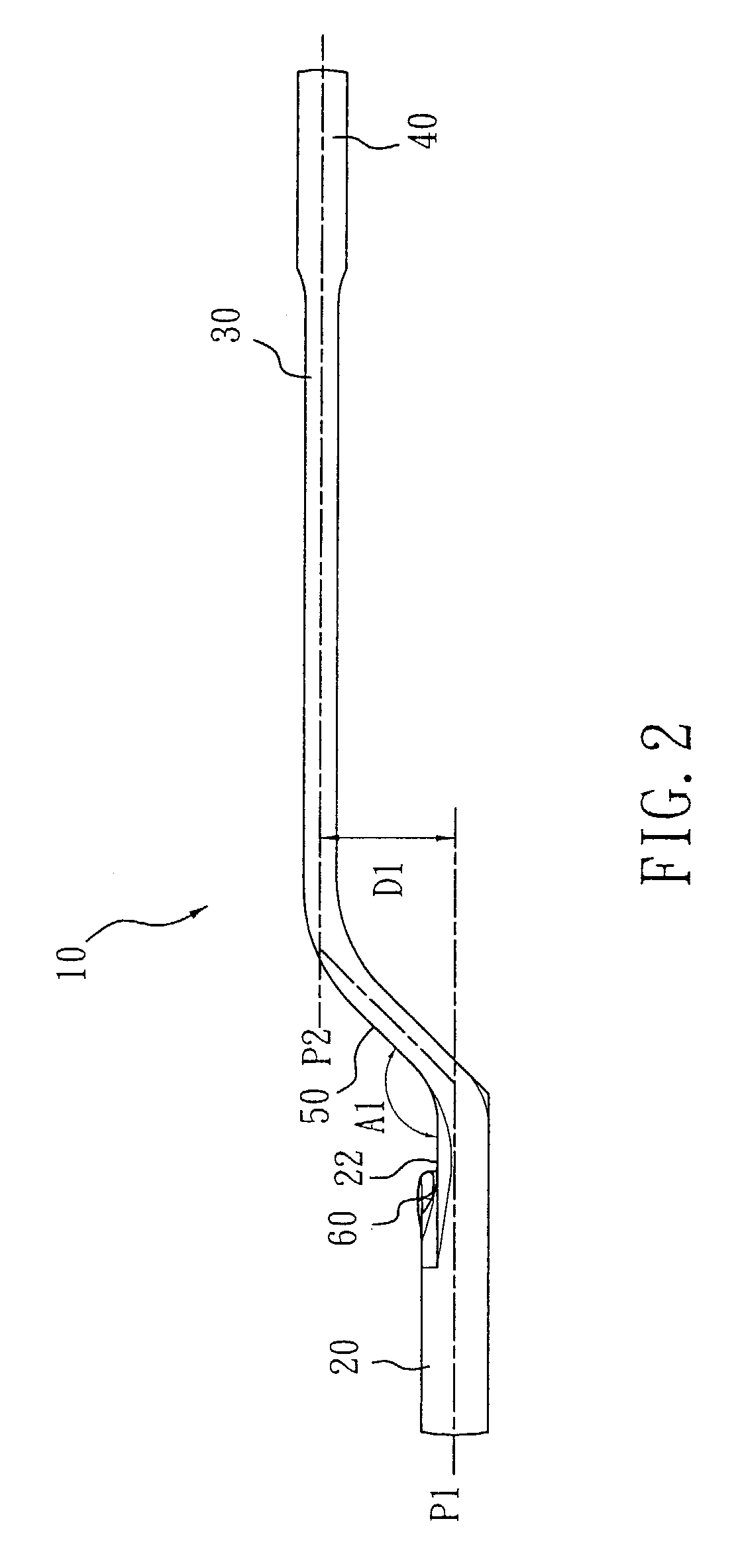
[0022] With reference to FIG. 2, the head 20 extends along a first plane P1 and the tail 30 extends along a second plane P2.

[0023] This invention is characterized in that, the first plane P1 is parallel to the second plane P2, and the neck 50 obliquely extends from the head 20 towards the tail 30 to form a height difference D1 between the head 20 and the tail 30.

[0024] In practical operation, it is found that it is preferred the height difference D1 formed between the first plane P1 on wh...


PUM


Abstract

A gear wrench allowing easy force application, having: a head, formed with a receiving compartment thereon for receiving a gear ring, the head extending along a first plane; a tail, extending along a second plane; and a neck, provided between and integrally formed with the head and the tail; characterized in that: the first plane is parallel to the second plane, and the neck obliquely extends from the head towards the tail to form a height difference between thee head and the tail. As such, the vertical component of force may be eliminated or minimized so as to effectively reduce occupational hazards; the horizontal component of force may also be increased such that the operator only requires a lower force to effectively tighten or loosen up a fastener.

Description

CROSS-REFERENCES TO RELATED APPLICATIONS[0001] Not Applicable[0002] Not Applicable[0003] This invention relates to a wrench, particularly to a gear wrench allowing easy force application.BACKGROUND OF INVENTION[0004] FIGS. 6A to 6C illustrate a conventional gear wrench with an angle formed between its head and tail, such that its tail inclines upwards with respect to its head. The purpose for providing the inclination is to form a height difference between its tail and open wrenching end to allow easy gripping by an operator. However, such a design fails to meet ergonomics because the operator's hand would need to incline for a certain degree along with the inclined tail.[0005] In addition, due to the inclination of the wrench, when the operator applies a force to cause its head to rotate a fastener (such as bolt), the operator's hand tends to turn the force of application in a horizontal direction so as to result in a vertical component of force Fh and a horizontal component of for...

Claims


Application Information

Patent Timeline
IPC IPC(8): B25B13/04B25B13/08B25B13/46B25G1/10
CPCB25B13/04B25B13/08B25B13/461B25B13/463B25G1/105
Inventor TUANMU, TOM
Owner DANAHER TOOL
Why Eureka
Try Eureka