

Head stabilizing system
a stabilizing system and head technology, applied in the direction of pedestrian/occupant safety arrangements, vehicular safety arrangements, transportation and packaging, etc., can solve the problems of high speed, high risk of high speed crash, rapid deceleration of vehicles,
- Summary
- Abstract
- Description
- Claims
- Application Information
AI Technical Summary
Problems solved by technology
Method used
Image

Examples
Embodiment Construction
[0002] 1. Field of the Invention
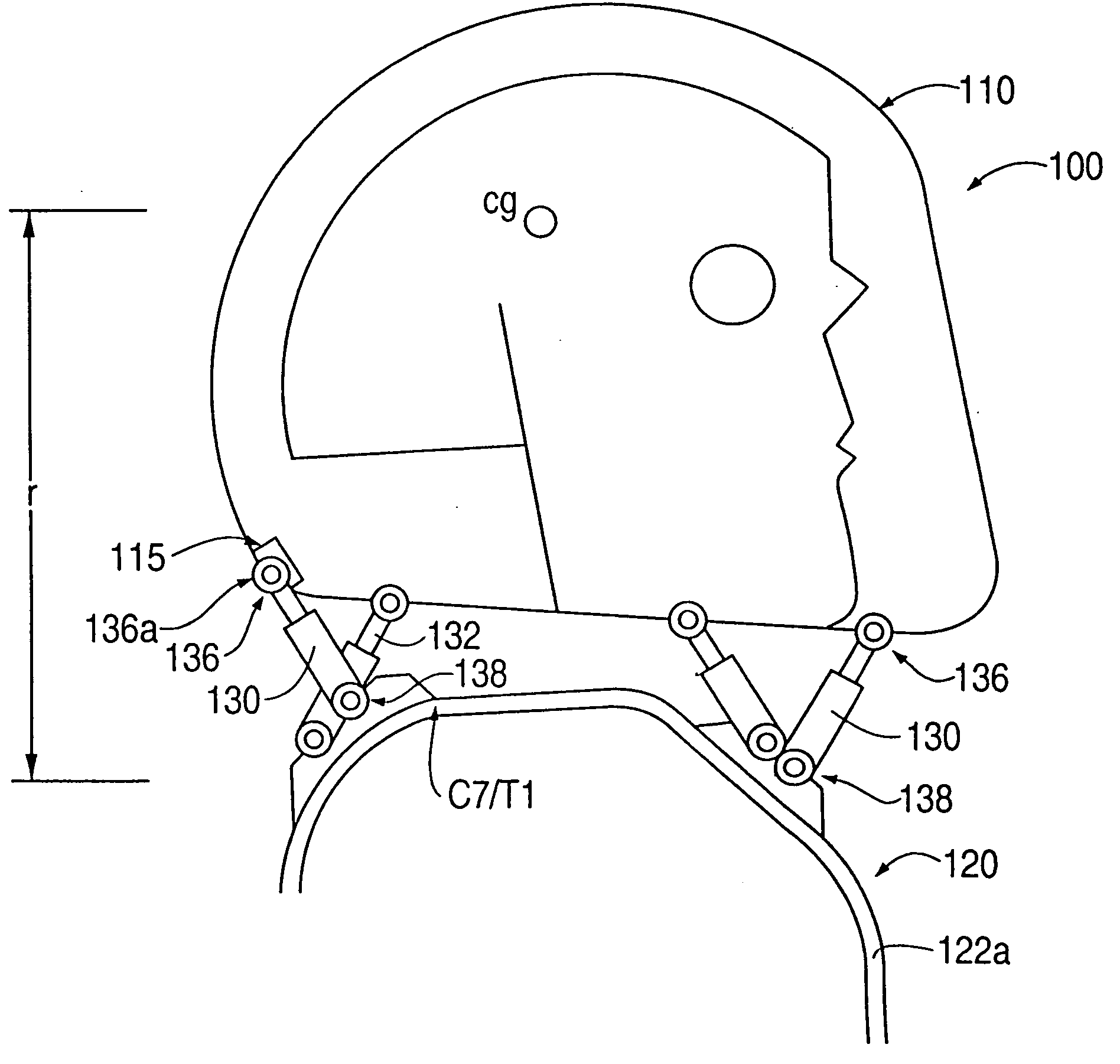
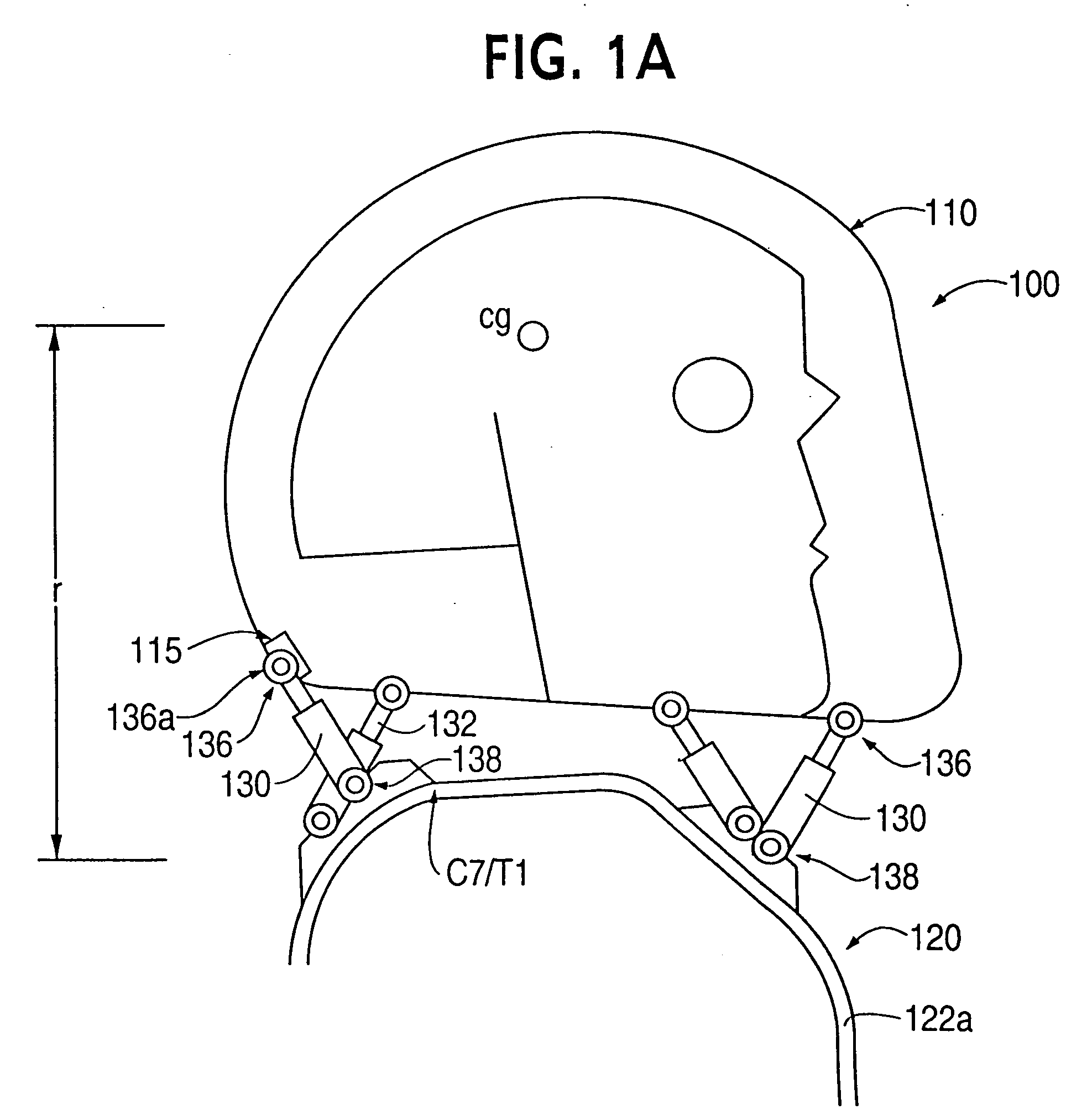
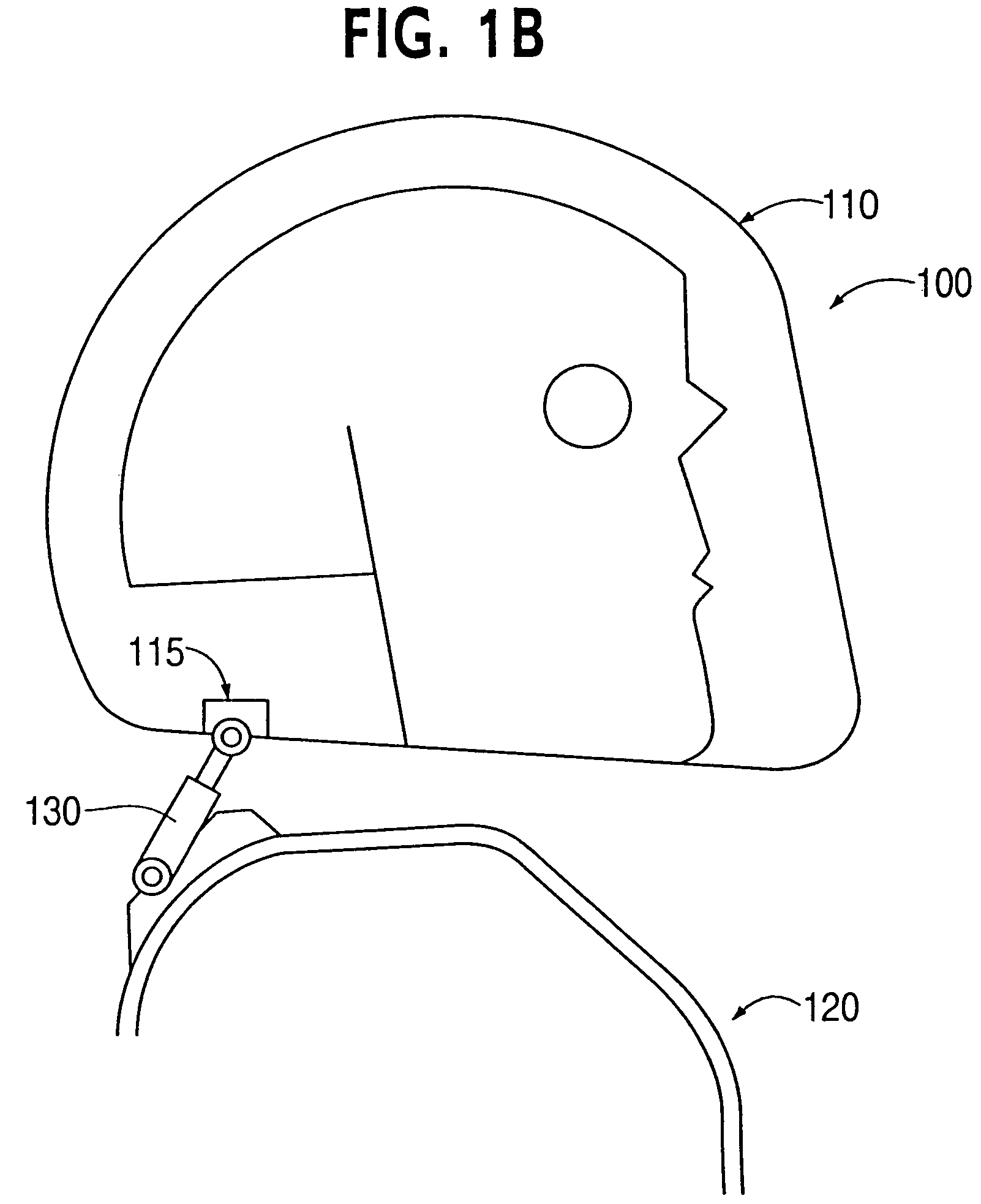
[0003] The present invention relates to a head stabilizing system for minimizing loads on the head and the neck, some of which may be injurious or even fatal, by generating a reaction force that substantially opposes a force acting on the head and generated by rapid deceleration of a vehicle or a crash impact.
[0004] 2. Background of the Invention
[0005] Activities that involve high speed, such as racing cars or boats and flying aircraft, involve a large risk of a high speed crash. Such crashes involve rapid deceleration of the vehicle and the portion of its occupant connected, via seatbelt or harness, to the vehicle. However, the head and the neck of the occupant are generally not connected to the seat, and thus the head of the occupant accelerates rapidly with respect to the body, exerting a large force on the base of the skull, the neck muscles, ligaments, and the spinal cord of the occupant, and creating a large risk for severe head and neck injurie...
PUM
 Abstract
Description
Claims
Application Information