Torsional vibration dampers

a technology of torsional vibration and dampers, which is applied in the direction of torsion springs, hoisting equipment, machines/engines, etc., can solve the problems of rotatable shaft fatigue failure, attachment that does not provide significant help, and torsional vibrations of considerable amplitude, so as to reduce the mass of the spoke portion

Inactive Publication Date: 2017-08-17
DAYCO IP HLDG
View PDF2 Cites 6 Cited by
  • Summary
  • Abstract
  • Description
  • Claims
  • Application Information

AI Technical Summary

Benefits of technology

[0009]Torsional vibration dampers having a dual spring-dashpot system are disclosed herein that result in a lightweight hub and a lightweight inertia ring. Surprisingly, not only can the mass of the spoke portion of the hub be reduced, but so can the mass of the inertia ring due to the presence of a secondary elastomer spring that contributes flexibility to the hub. The mass of the spoke portion may be reduced by using phenolic material or non-metallic composite material for its construction.
[0012]In all embodiments, the inertia ring has a polar moment of inertia of about 1000 kg-mm2 to about 40,000 kg-mm2, and the dual spring-dashpot system increases the reaction torque of the inertia ring, as a harmonic response reaction moment at unit torque input at the outer diameter of the inertia ring, by at least a factor of 1.5 at its peak.

Problems solved by technology

The torsional vibrations may be of considerable amplitude, and, if not abated, can potentially damage gears or similar structures attached to the rotatable shaft and cause fatigue failure of the rotatable shaft.
This otherwise implies that the hub is, in fact, a rigid attachment that does not provide any significant help to the damping system except to provide a rigid means of connection to the rotating component of the vehicle.
Attempts have been made to use a phenolic material for the hub of a TVD, but none have resulted in a commercially suitable TVD because this material lacks the fatigue strength required to function as a hub.

Method used


Image

  • Torsional vibration dampers
  • Torsional vibration dampers
  • Torsional vibration dampers

Examples


Embodiment Construction

[0032]The following detailed description will illustrate the general principles of the invention, examples of which are additionally illustrated in the accompanying drawings. In the drawings, like reference numbers indicate identical or functionally similar elements.

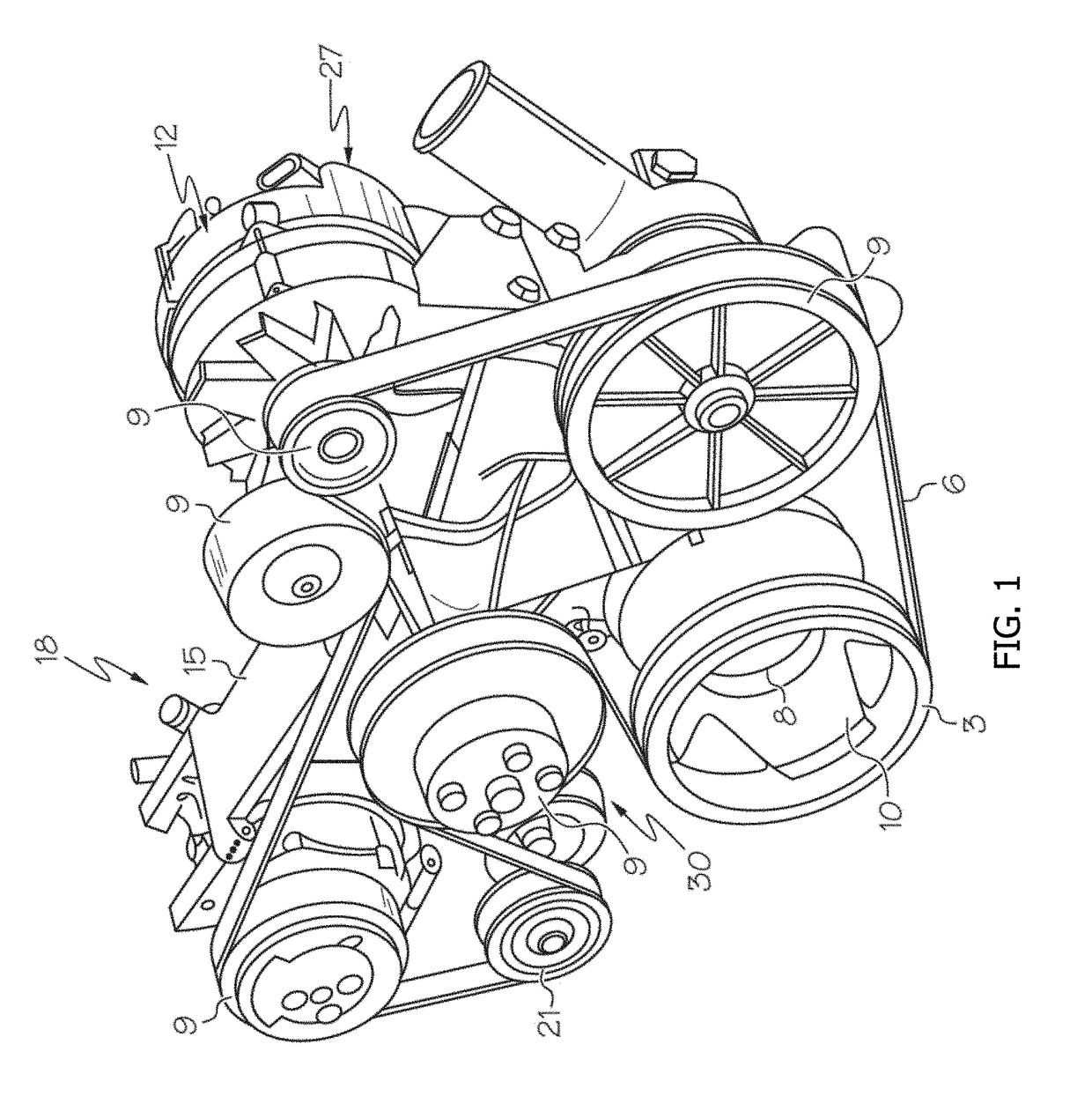
[0033]Referring now to FIG. 1, an example of one embodiment of an FEAD system 18 is shown, merely for illustration purposes, that includes an integrated housing 15, having a front surface 30 and a rear surface 27. The rear surface 27 of the integrated housing 15 is preferably mounted to an engine. The FEAD system 18 may be utilized with any engine, including vehicle, marine and stationary engines. The shape and configuration of the integrated housing 15 depends upon the vehicle engine to which it is to be mounted. Accordingly, the integrated housing 15, and more specifically the FEAD system 18, may vary along with the location of engine drive accessories 9, including idler pulleys. It should be understood that the locati...


PUM


Abstract

Torsional vibration dampers having a dual spring-dashpot system are disclosed that result in a lightweight hub and a lightweight inertia ring, which is concentric about the hub. The hub has a two-piece construction: a central hub defining an innermost sleeve that defines a bore for receiving a shaft; and a monolithic, generally-annular spoke defining an outermost ring concentric about and spaced radially outward from the central hub portion. A first elastomer member, which acts as a primary spring to damp torsional vibrations, is positioned concentrically against an inner surface or an outer surface of the outermost ring of the hub with the inertia ring concentrically positioned against the first elastomer member. A second elastomer member is positioned between and operatively couples the central hub to the annular spoke, thereby attributing a flexibility to the hub.

Description

RELATED APPLICATIONS[0001]This application claims the benefit of U.S. Provisional Application No. 62 / 295,021, filed Feb. 13, 2016, which is incorporated by reference herein in its entirety.FIELD OF THE INVENTION[0002]The present invention relates to torsional vibration dampers, more particularly torsional vibrations dampers having a reduced mass for a spoke portion of a hub that is operatively coupled to a central hub by a secondary elastomer spring and a reduced mass for an inertia ring, which is operatively coupled to the spoke portion by a primary elastomer spring, thereby forming a dual dashpot system.BACKGROUND OF THE INVENTION[0003]Torsional vibration dampers (“TVDs”) are employed extensively in internal combustion engines to reduce torsional vibrations delivered to rotatable shafts. The torsional vibrations may be of considerable amplitude, and, if not abated, can potentially damage gears or similar structures attached to the rotatable shaft and cause fatigue failure of the r...

Claims


Application Information

Patent Timeline
Patent Type & Authority Applications(United States)
IPC IPC(8): F16H55/36F02B67/06F16F15/121
CPCF16H55/36F16F15/1216F16H2055/366F16F2238/024F02B67/06F16F15/126F16F15/1442
Inventor MANZOOR, SUHALE
Owner DAYCO IP HLDG
Why Eureka
Try Eureka