Water discharge switching device

Inactive Publication Date: 2005-01-06
TOTO LTD
View PDF3 Cites 16 Cited by
  • Summary
  • Abstract
  • Description
  • Claims
  • Application Information

AI Technical Summary

Benefits of technology

[0088] In this manner, it is possible to prevent a water leak caused by flowing water to the air suction port side at the time when the foaming water is discharged and at the same time, to pack the gap produced between the connection portion of t

Problems solved by technology

However, in this conventional water discharge switching device, as the air suction port of the foaming water producing and discharging means and the shower water discharge port of the shower water discharging means are provided separately from each other, a problem is presented in that it i

Method used


Image

  • Water discharge switching device
  • Water discharge switching device
  • Water discharge switching device

Examples


Example

[0118] First, a water discharge switching device in accordance with a first embodiment of the present invention will be described.

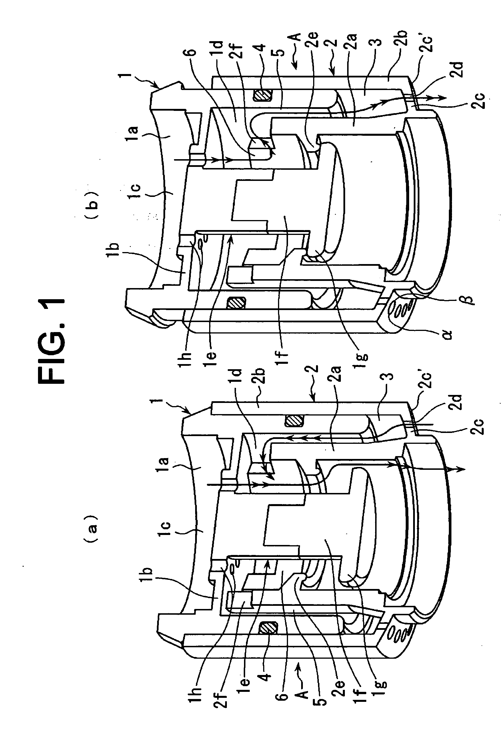
[0119] As shown in FIG. 1, a water discharge switching device A has a first cylindrical body 1. A fitting portion 1a to be fitted to an existing faucet is formed at one end of the first cylindrical body 1. Near the fitting portion 1a is formed a partition wall 1b. An inflow chamber 1c and a discharge chamber 1d which are adjacent to each other in a longitudinal direction of the first cylindrical body 1 are defined by the partition wall 1b. The inflow chamber 1c is opposed to the fitting portion 1a.

[0120] A pillar-shaped body 1e extends in a longitudinal direction from the central portion of the partition wall 1b to form the discharge chamber 1d in an annular shape. A flange-shaped valve seat 1g is formed at an end portion 1f of the pillar-shaped body 1e. The end portion 1f of the pillar-shaped body 1e is formed separately from the other parts of the fir...

Example

[0141] A water discharge switching device in accordance with a second embodiment of the invention will be described.

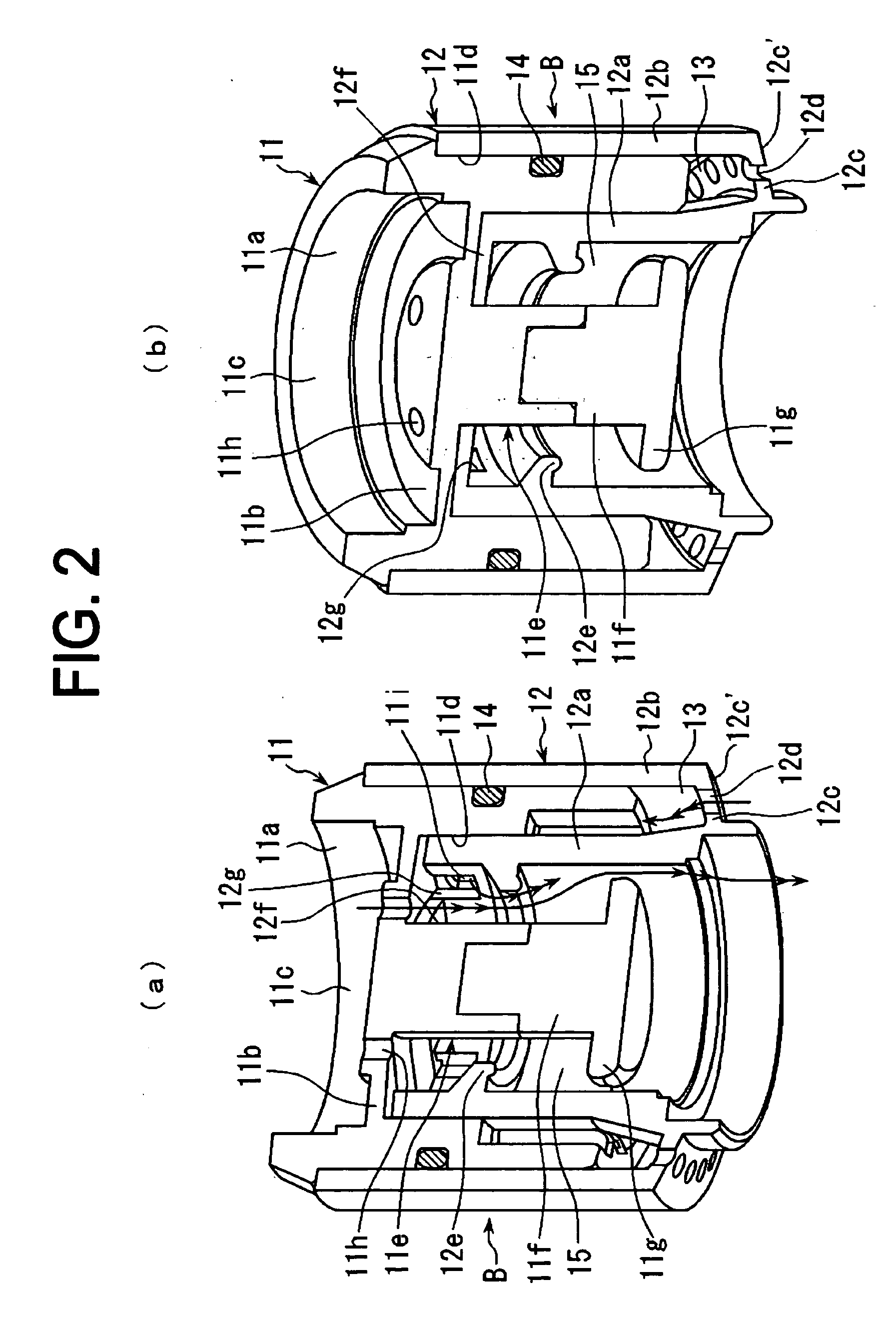
[0142] As shown in FIG. 2 to FIG. 4, a water discharge switching device B has a first cylindrical body 11. A fitting portion 11a to be fitted on an existing faucet is formed at one end of the first cylindrical body 11. Near the fitting portion 11a is formed a partition wall 11b. An inflow chamber 11c and a discharge chamber 11d which are adjacent to each other in a longitudinal direction of the first cylindrical body 11 are partitioned by the partition wall 11b. The inflow chamber 11c faces the fitting portion 11a.

[0143] A pillar-shaped body 11e extends in a longitudinal direction from the central portion of the partition wall 11b to form the discharge chamber 11d in an annular shape. A flange-shaped valve seat 11g is formed at an end portion 11f of the pillar-shaped body 11e. The end portion 11f of the pillar-shaped body 11e is formed separately from the other parts...

Example

[0175] A water discharge switching device in accordance with a third embodiment of the present invention will be described.

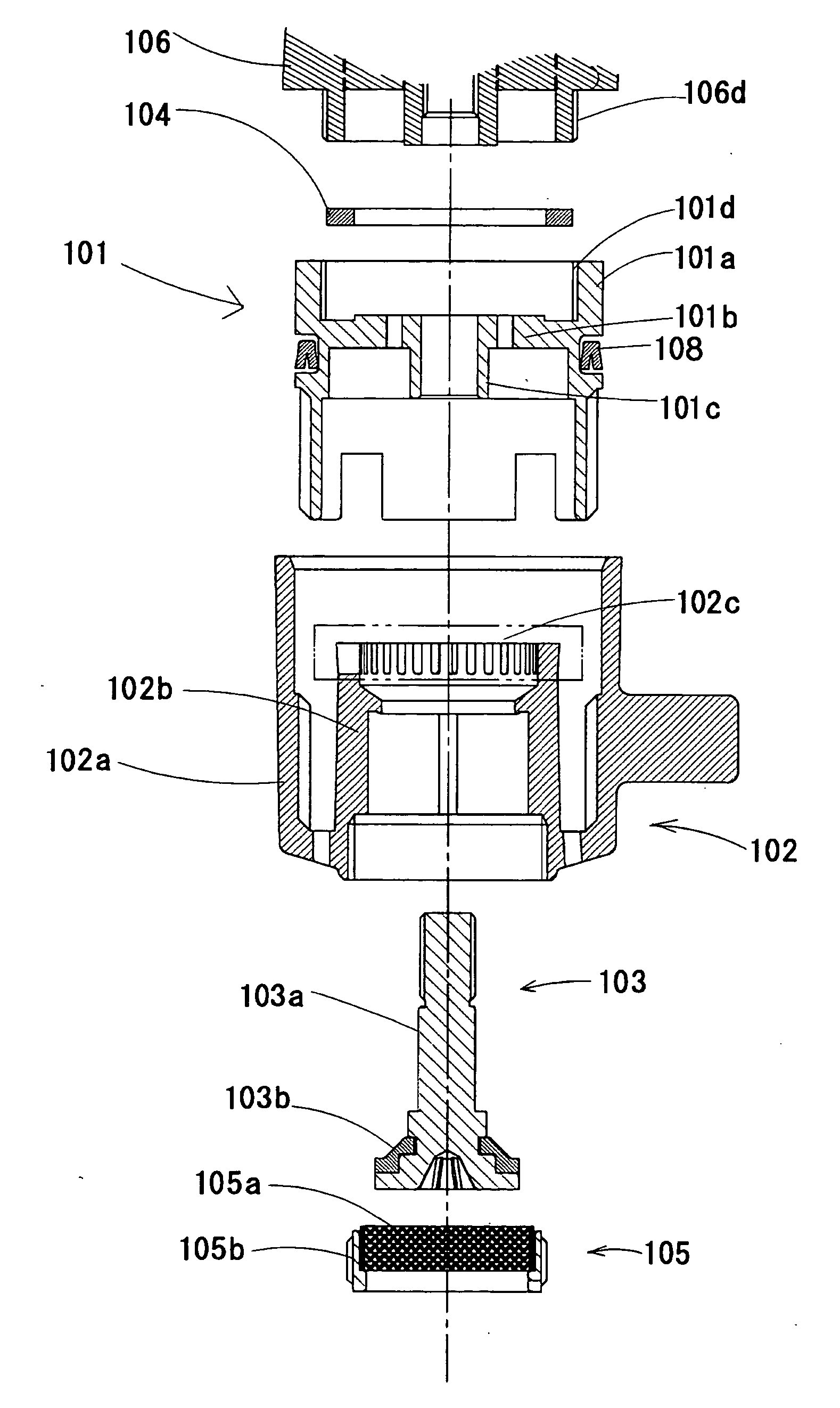
[0176] In FIG. 5 are shown constituent parts of an example of a water discharge switching device of the invention and in FIG. 6 is shown a cross-sectional view showing a state in which the water discharge switching device is switched to a state of discharging foaming water.

[0177] This water discharge switching device includes a first cylindrical body 101, a second cylindrical body 102, a flange-shaped valve seat 103, a packing 104, a filter part 105, and a U-shaped packing 108, these parts being assembled, and is fitted for use on a faucet hardware unit 106.

[0178] A fitting portion 101a to be fitted to the faucet hardware unit is formed at one end of the first cylindrical body 101 and a partition wall 101b is formed near the fitting portion 101a. A-pillar-shaped body 101c is formed so as to extend in a longitudinal direction from the central portion of the pa...


PUM


Abstract

A water discharge switching device which is easily miniaturized, readily assembled, and manufactured at low cost and prevents leakage of water. The water discharge switching device includes foaming water producing and discharging means having a water inlet (1c), an air/water mixing chamber facing the water inlet (1c) and capable of communicating with the water inlet (1c), an air suction port capable of communicating with the air/water mixing chamber, and a foaming water outlet; shower water discharging means having a shower water discharge port (2d) and capable of communicating with the water inlet (1c), the shower water discharging means being arranged around the air/water mixing chamber of the foaming water producing and discharging means; and water discharge switching means for selectively switching between the discharge of foaming water from the foaming water producing and discharging means and the discharge of shower water from the shower water discharging means. The shower water discharge port (2d) of the shower water discharging means forms the air suction port of the foaming water producing and discharging means.

Description

TECHNICAL FIELD [0001] The present invention relates to a water discharge switching device capable of switching a water discharge mode between the discharge of foaming water and the discharge of shower water. BACKGROUND ART [0002] A conventional water discharge switching device has been used including: a foaming water producing and discharging means having a water inlet, an air / water mixing chamber and capable of communicating with the water inlet, an air suction port capable of communicating with the air / water mixing chamber, and a foaming water outlet; shower water discharging means having a shower water discharge port and capable of communicating with the water inlet, the shower water discharging means being arranged around the air / water mixing chamber of the foaming water producing and discharging means; and water discharge switching means for selectively switching between the discharge of foaming water from the foaming water producing and discharging means and the discharge of ...

Claims


Application Information

Patent Timeline
IPC IPC(8): E03C1/04E03C1/084E03C1/086
CPCE03C1/084
Inventor TAKETOMI, YOUJIROUTAKEBAYASHI, YASUHIROMIYAGI, TAKAFUMI
Owner TOTO LTD
Why Eureka
Try Eureka