Headlight assembly having vertical headlamp adjuster

Inactive Publication Date: 2005-01-06
VARROC LIGHTING SYST
View PDF11 Cites 4 Cited by
  • Summary
  • Abstract
  • Description
  • Claims
  • Application Information

AI Technical Summary

Benefits of technology

[0005] The present invention overcomes the disadvantages of prior designs by providing a less complex adjustment mechanism for a headlight assembly. The headlight assembly of the present invention includes a headlight housing, a reflector positioned within and pivotally connected to the housing by at least two connection or pivot points, an adjuster clip connected to the reflector, and an adjuster screw that is partially received within the clip and threadably engaged with the assembly's housing. For convenience and ease of use, the adjuster is accessible from the top of the headlight assembly. As torque is applied to the adjuster screw, the entire reflector radially pivots about a transverse horizontal pivot axis, which is defined by the connection points. Accordingly, the aim of the headlight is vertically adjusted.

Problems solved by technology

Known adjustment mechanisms use complex, multi-component systems.
One disadvantage of this type of system is that it is more likely to bind due to the horizontal displacement of its pivot in a constant vertical plane.
These types of systems are difficult to access due to the tight packaging of the components under the hood of the vehicle.

Method used


Image

  • Headlight assembly having vertical headlamp adjuster
  • Headlight assembly having vertical headlamp adjuster
  • Headlight assembly having vertical headlamp adjuster

Examples


Embodiment Construction

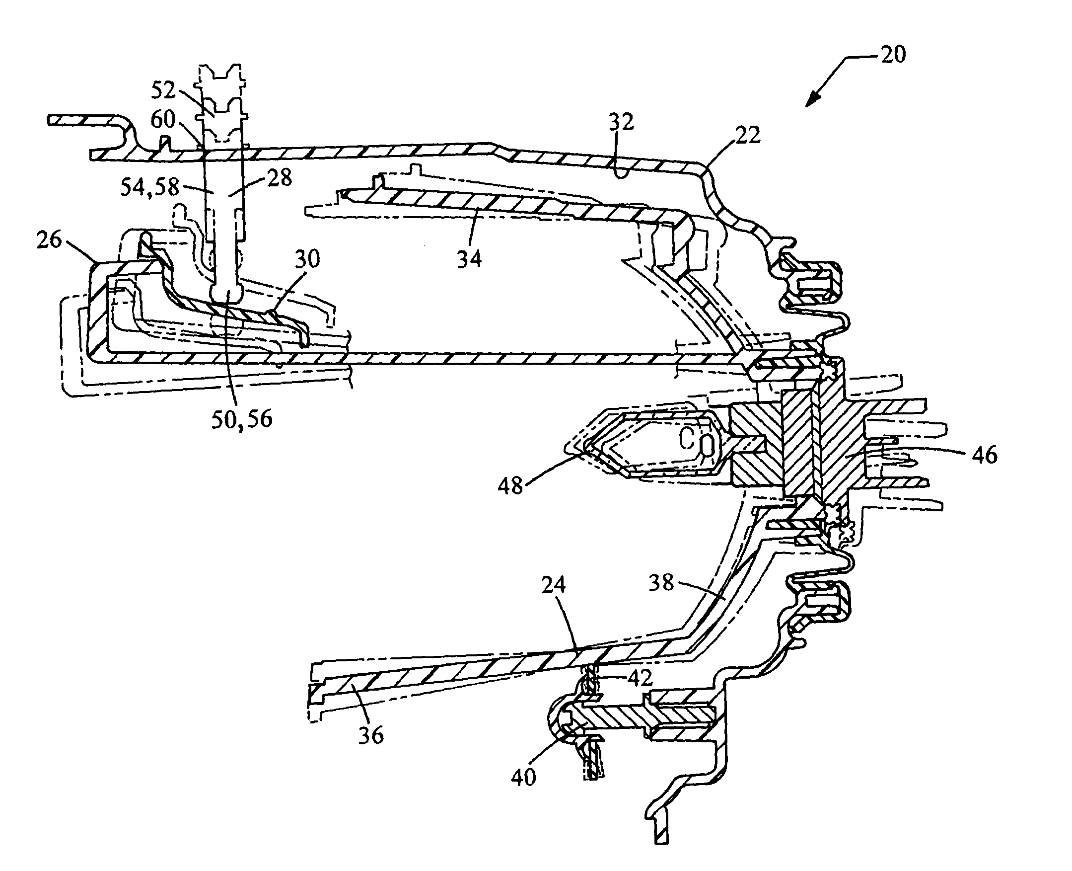
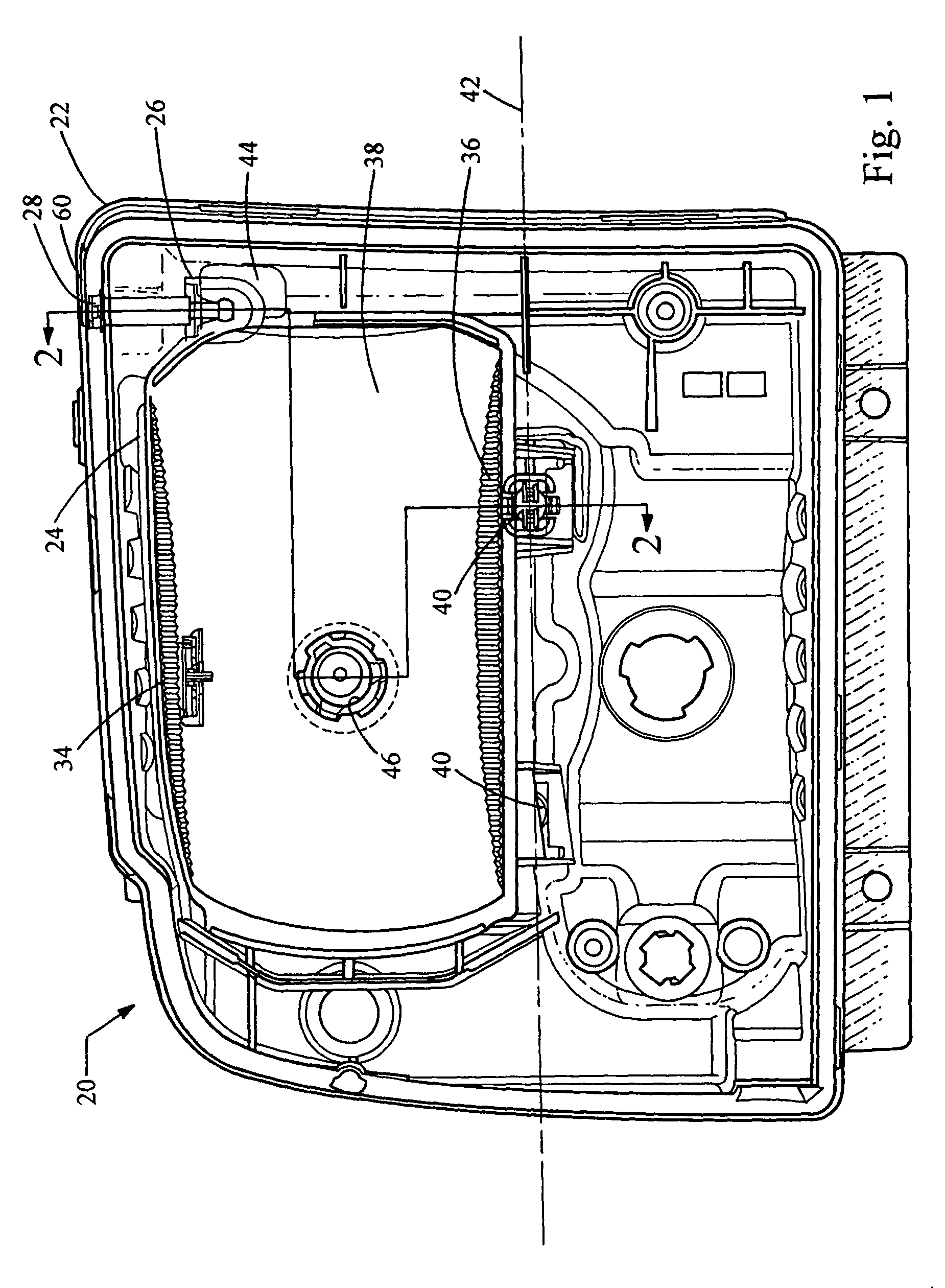
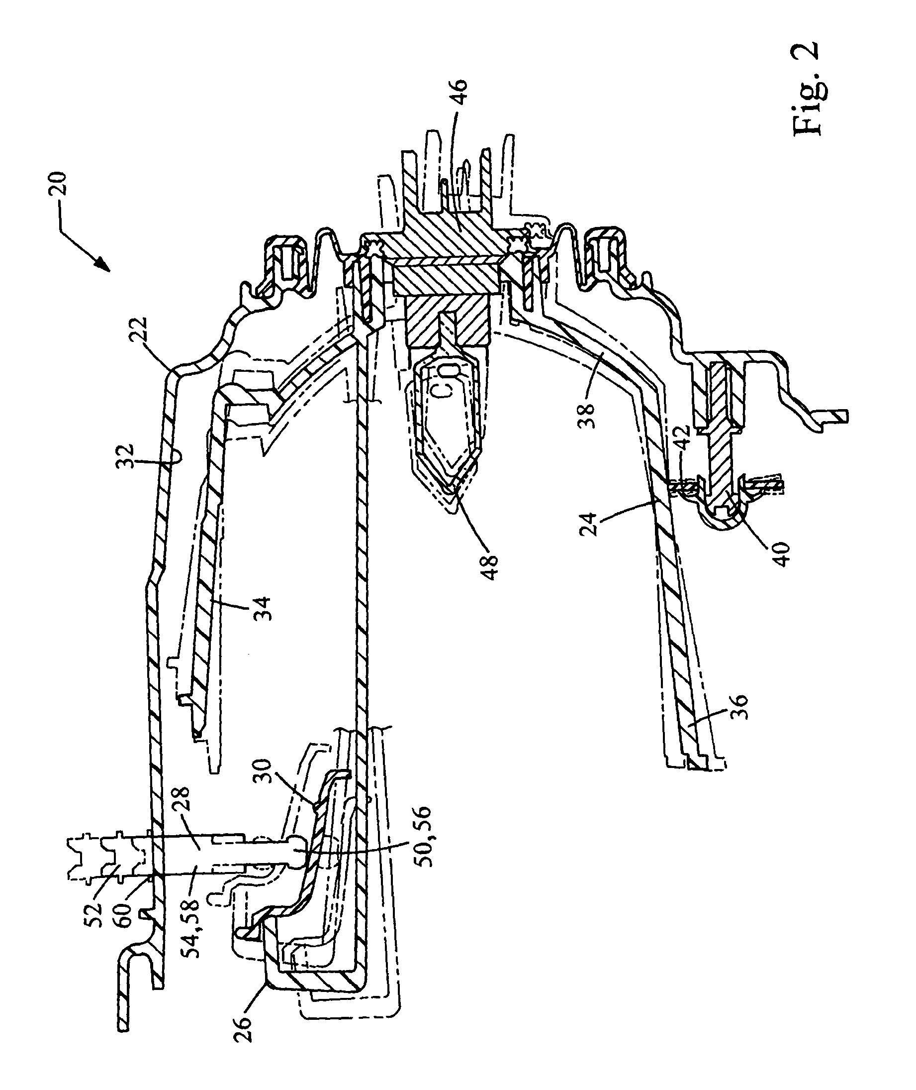
[0011] Referring now to the drawings, FIG. 1 generally illustrates a headlight assembly 20 embodying the principles of the present invention and specifically adapted for use in a motor vehicle (not shown). The headlight assembly 20 includes as its primary components, a housing 22, a reflector 24, an adjustment assembly 26 and a pair of pivots 40. Preferably, two headlight assemblies 20 are mounted to the front of a vehicle, one located on each side thereof.

[0012] The housing 22 is connected to the frame of the vehicle through one or more mounting bores 31. Accordingly, the housing 22 is fixed in a stationary position relative to the vehicle.

[0013] In the illustrated embodiment, the housing 22 defines a recessed cavity 32 for receipt of the reflector 24. The reflector 24 itself is defined by a top wall 34, a bottom wall 36, and a curved rear wall 38 extending between the top and bottom walls 34, 36 that also defines the sides of the reflector 24. (Directional references used herein...


PUM


Abstract

A vertically adjustable headlight assembly having a headlight housing, a reflector positioned within the housing and an adjuster mechanism including a channel and an adjustment member. An end of the adjustment member is accessible outside of the housing and the other end is received in the channel. When advanced or retracted, the end of the adjustment member travels within the channel causing the reflector to pivot within the housing and vertically adjust.

Description

TECHNICAL FIELD [0001] This invention generally relates to a headlight assembly and, more specifically, to a headlight assembly having a vertical headlight adjustment mechanism.DESCRIPTION OF THE RELATED ART [0002] It is well known to use adjustment mechanisms to align the vertical and horizontal position of a vehicle's headlight with respect to the vehicle itself. Known adjustment mechanisms use complex, multi-component systems. [0003] One such system, generally known as a “right angle adjuster”, includes two shafts positioned perpendicular to each other, joined by a gear box and attached to the reflector. One disadvantage of this type of system is that it is more likely to bind due to the horizontal displacement of its pivot in a constant vertical plane. Other known systems utilize constant adjusters that are accessed from the rear of the headlight housing. These types of systems are difficult to access due to the tight packaging of the components under the hood of the vehicle. [0...

Claims


Application Information

Patent Timeline
IPC IPC(8): B60Q1/068
CPCB60Q1/0683
Inventor LEATHLEY, ROBERT A.SANFREY, JEFFREY S.KALIS, EDWARD M.MCCARTHY, STEPHEN D.STOI, GREGORY A.FASSETT, JAMES
Owner VARROC LIGHTING SYST
Why Eureka
Try Eureka