Two-way RF ranging system and method for local positioning

Active Publication Date: 2005-01-06
DEERE & CO
View PDF31 Cites 83 Cited by
  • Summary
  • Abstract
  • Description
  • Claims
  • Application Information

AI Technical Summary

Benefits of technology

The system and method of the present invention provide a low-cost, yet highly accurate, local positioning system. Radio frequency (RF) signals are exchanged amongst devices to determine times of flight between the devices. The propagation speed of the RF signals does not vary as

Problems solved by technology

Global positioning systems such as GPS provide only medium accuracy position information, usually no better than 10 cm, and requires a clear view of the sky to near the horizon.
Unfortunately, because of the properties of sound propagation throu

Method used


Image

  • Two-way RF ranging system and method for local positioning
  • Two-way RF ranging system and method for local positioning
  • Two-way RF ranging system and method for local positioning

Examples


Example

DETAILED DESCRIPTION OF THE DRAWINGS

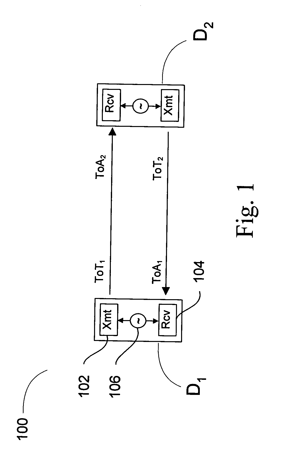
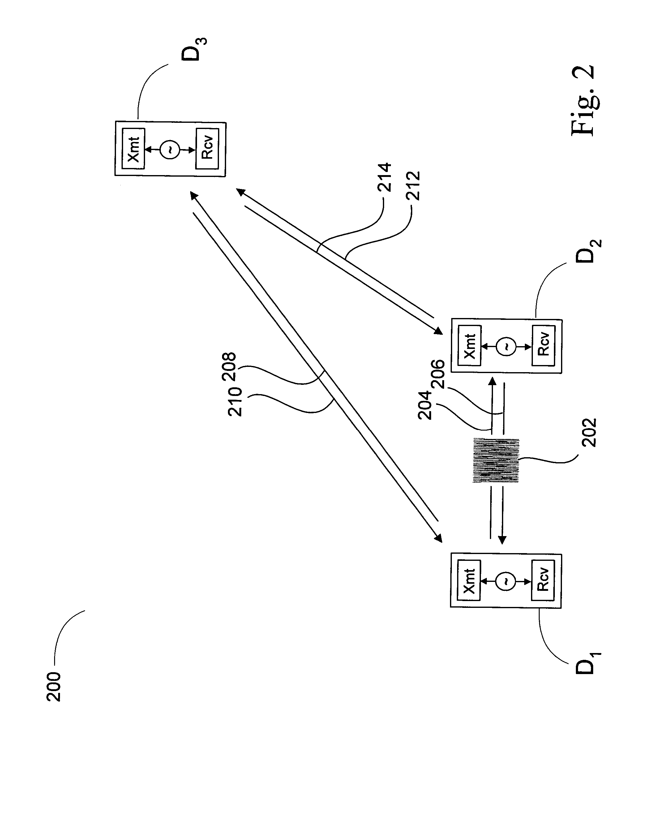
Many conventional local positioning systems use time of flight measurements of a signal sent from a transmitter to a receiver to determine a respective range between the transmitter and the receiver. In some systems, the receiver is located on a device whose position is unknown and the transmitter on a device whose position is known. If there are a sufficient number of devices whose positions are known, the device whose position is unknown can receive transmissions from each of the devices whose positions are not known, determine the time of flight from each of these devices, determine the range to each of these devices, and subsequently trilateralate its own position.

For a receiver to determine the time of flight between a transmitter and the receiver using the time of arrival of the transmitted signal, the receiver must know the time at which the transmitter sent the signal. In some positioning systems, the transmitter may transmit at a time...


PUM


Abstract

A positioning system includes a plurality of devices configured to exchange RF signals with one another. A first device periodically receives a message from each other device during time slots assigned them. The received message includes information representing a time of arrival at the other device of a respective message transmitted by the first device. A time of arrival of the message from each of the other devices is determined by the first device. The first device periodically transmits messages to the other devices, each transmitted message including information representing the determined time of arrival for at least one of the other devices. A range from the first device to each of a plurality of the other devices is determined as function of the determined time of arrival of the message from the other device and the time of arrival information in the message from the other device.

Description

FIELD OF THE INVENTION The present invention relates generally to positioning systems, and, more specifically, to an apparatus and method for operating a positioning system in which a plurality of devices exchange messages with one another, enabling at least one of the devices to determine the relative positions of at least one other device in the system based on the information in, and time-of-arrival of, the message received from the other device. BACKGROUND OF THE INVENTION Local positioning systems are becoming an important enabler in mobile devices requiring navigation capabilities, especially in applications of autonomous vehicles and precision construction tools. Global positioning systems such as GPS provide only medium accuracy position information, usually no better than 10 cm, and requires a clear view of the sky to near the horizon. Local positioning systems, with either active or passive components distributed in a working volume, can allow much more accurate (<1...

Claims


Application Information

Patent Timeline
IPC IPC(8): G01S5/02G01S19/11G01S5/14H04J3/06H04L7/00H04Q7/38
CPCG01S5/021G01S11/08G01S5/14G01S5/0289
Inventor WOO, RICHARD KAI-TUENRENTZ, MARK LINDSAYSTEPHENS, SCOTT ADAMKAPLAN, MARK PHILLIPWOO, ANDREAWOO, RUSSELL
Owner DEERE & CO
Why Eureka
Try Eureka