Filter assembly for vacuum cleaner

a vacuum cleaner and filter assembly technology, applied in the field of vacuum cleaners, can solve the problems of frequent replacement of filters, inconvenient cleaning of accumulated dust and dirt, etc., and achieve the effect of prolonging the life of filters and quick and convenient cleaning operations

Inactive Publication Date: 2005-01-13
LG ELECTRONICS INC
View PDF23 Cites 16 Cited by
  • Summary
  • Abstract
  • Description
  • Claims
  • Application Information

AI Technical Summary

Benefits of technology

[0013] The present invention is conceived to solve the aforementioned problems in the prior art. Accordingly, an object of the present invention is to provide a filter assembly for a vacuum cleaner, capable of easily removing dust and dirt accumulated in a filter during in the process of filtering the fine dust contained in air.
[0019] According to the filter assembly of the present invention so constructed, there are advantages in that the filter cleaning operation can be quickly and conveniently performed and life of the filter can be prolonged.

Problems solved by technology

Therefore, there is inconvenience in that the accumulated dust and dirt should be repeatedly cleaned.
Further, there is a problem in that if the fine dust and dirt are continuously accumulated in the fine filter, the filter should be frequently replaced with a new one.

Method used


Image

  • Filter assembly for vacuum cleaner
  • Filter assembly for vacuum cleaner
  • Filter assembly for vacuum cleaner

Examples


Embodiment Construction

[0028] Hereinafter, preferred embodiments of a dust collecting unit for a vacuum cleaner according to the present invention will be described in detail with reference to the accompanying drawings. Throughout the drawings, like reference numerals are used to designate like elements.

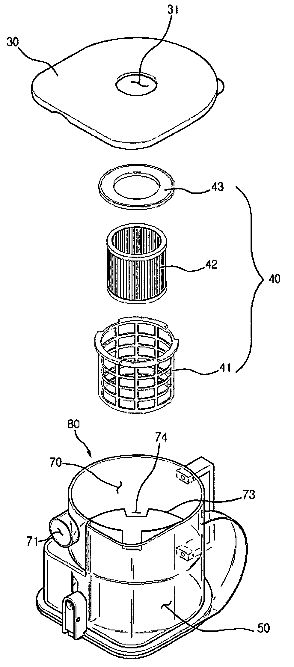
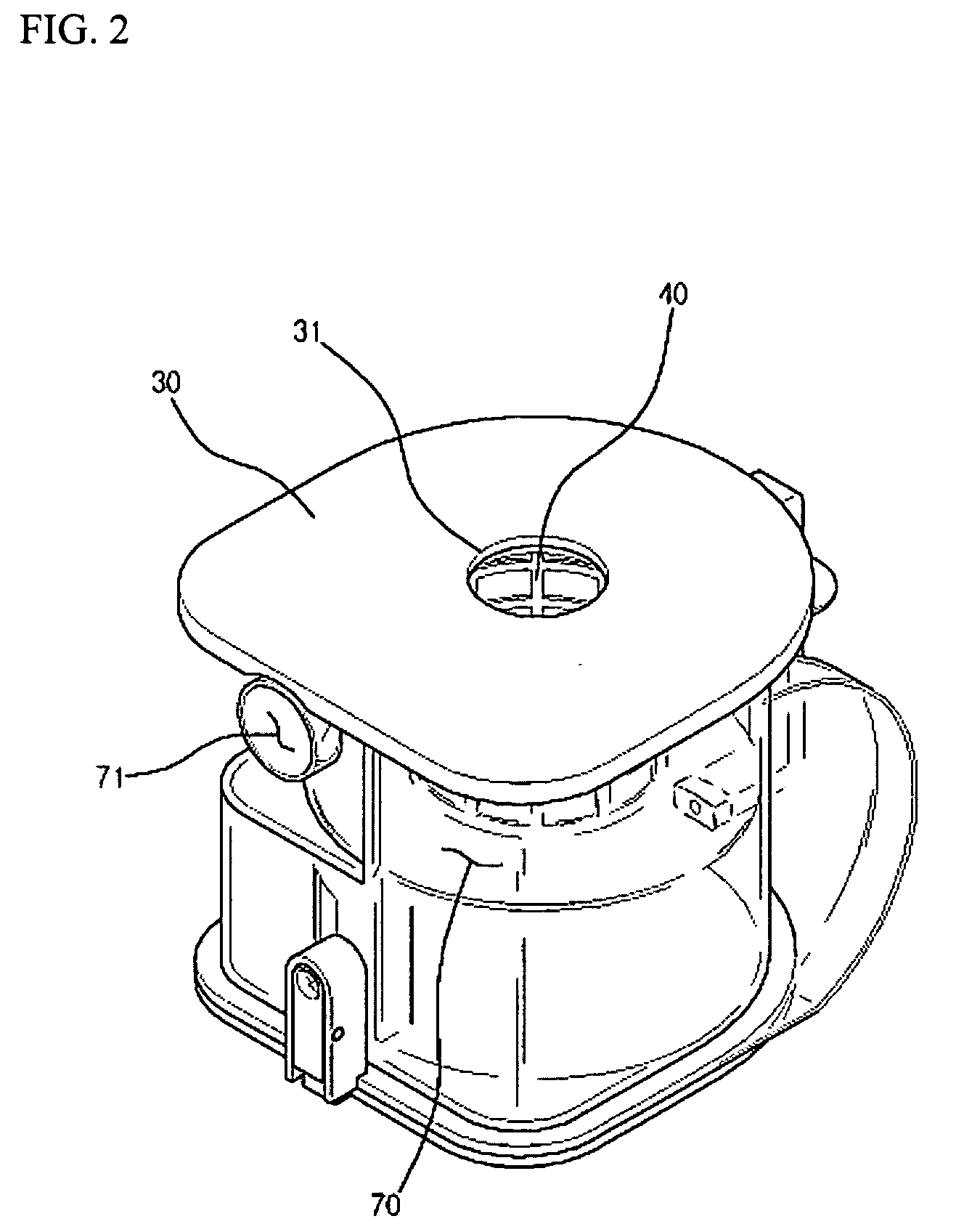
[0029]FIG. 2 is a front perspective view of a dust collecting unit of a cyclonic vacuum cleaner according to the present invention, and FIG. 3 is an exploded perspective view of the dust collecting unit of the cyclonic vacuum cleaner according to the present invention.

[0030] Referring to FIGS. 2 and 3, the vacuum cleaner of the present invention comprises a cover 30 for covering an upper end of the dust collecting unit 11 to protect inner parts and hermetically sealing the unit to prevent sucked air from leaking out, a filter assembly 40 installed downward from the cover 30 around an outlet 31 formed near the center of the cover, and a dust collecting casing 80 attached to a bottom side of the cover 30. ...


PUM

PropertyMeasurementUnit
surface areaaaaaaaaaaa
flexibleaaaaaaaaaa
speedaaaaaaaaaa

Abstract

A filter assembly for a vacuum cleaner according to the present invention comprises a primary filter for filtering out fine dust contained in air from which relatively large dust has been separated in a cyclonic manner, a filter case with the primary filter attached to an outer periphery thereof and a plurality of air vent holes formed on the outer periphery thereof, and a secondary filter mounted into the filter case for filtering out again fine dust contained in the air which has passed through the primary filter. According to the present invention, it is possible to easily remove the dust and dirt accumulated in the filter assembly during the process of filtering the fine dust contained in the air, and the filter can be used semi-permanently.

Description

BACKGROUND OF THE INVENTION [0001] 1. Field of Invention [0002] The present invention relates to a vacuum cleaner, and more particularly, to a vacuum cleaner having an improved inner filter structure for a dust collecting unit thereof. [0003] 2. Description of the Prior Art [0004] A vacuum cleaner is an apparatus which sucks air containing foreign materials using a vacuum pressure generated by a vacuum motor installed in a main body of the vacuum cleaner, filters out foreign materials such as the dust and dirt in the main body, and then collects and discharges the dust and dirt. [0005] A cyclonic vacuum cleaner which has recently been widely used is designed to filter out dust and dirt in such a manner that relatively heavy dust and dirt are moved outward by a centrifugal force in air flow swirling at a high speed and collected in a specific dust collecting chamber, whereas fine dust and dirt which are not filtered out by the cyclonic method are filtered by a filter such as a pleate...

Claims


Application Information

Patent Timeline
Patent Type & Authority Applications(United States)
IPC IPC(8): A47L9/12A47L9/16A47L9/10B01D50/00
CPCA47L9/127B01D50/002A47L9/1666Y10S55/03B01D50/20
Inventor LEE, YUN-SEOKJEONG, HOI-KIL
Owner LG ELECTRONICS INC
Why Eureka
Try Eureka