Apparatus for measuring velocity and flow rate of a fluid having a non-negligible axial mach number using an array of sensors

a technology of axial mach number and actuator, applied in the direction of measuring devices, volume/mass flow by dynamic fluid flow effect, instruments, etc., can solve the problems of invasiveness of typical meters and not without drawbacks

Active Publication Date: 2005-01-13
EXPRO METERS
View PDF56 Cites 61 Cited by
  • Summary
  • Abstract
  • Description
  • Claims
  • Application Information

AI Technical Summary

Benefits of technology

The present invention aims to provide a new technology that can achieve specific objectives. The technical effects of the invention will be explained in detail in the following description of exemplary embodiments.

Problems solved by technology

The technical problem addressed in this patent text is the need for a non-invasive method to measure the velocity and flow rate of a fluid within a pipe in a fluid system, particularly in a system based on saturated vapor/liquid mixtures. The current methods are invasive and require at least a portion of the fluid system to be isolated.

Method used


Image

  • Apparatus for measuring velocity and flow rate of a fluid having a non-negligible axial mach number using an array of sensors
  • Apparatus for measuring velocity and flow rate of a fluid having a non-negligible axial mach number using an array of sensors
  • Apparatus for measuring velocity and flow rate of a fluid having a non-negligible axial mach number using an array of sensors

Examples


examples

The method of flow measurement described herein was demonstrated on a 6-inch schedule 40 steel pipe flowing air at near atmospheric pressure. The Mach number range was 0.07 to 0.16. A six-sensor PVDF mono-band was used to measure the acoustic field in the pipe, similar to that described in U.S. Provisional Patent Application, Ser. No. 60 / 451,685 filed Mar. 4, 2003 (Cidra's Docket No. CC-0599), which in incorporated herein by reference. A reference measurement was made with an orifice plate that had a relatively high uncertainty estimated at 5-10%. The results of one series of tests are shown in FIG. 4.

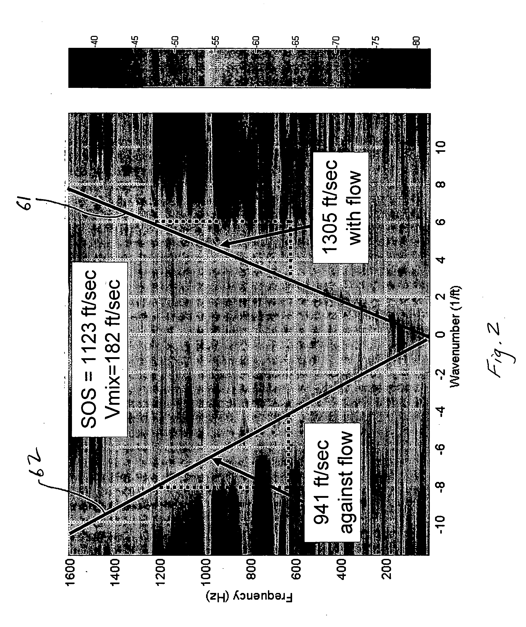
A typical k-ω plot of the data is as shown in FIG. 2. Note that the slope of the acoustic ridge 61 with positive wavenumber is greater than the slope of the acoustic ridge 62 with negative wavenumber indicating that the apparent speed in the direction of the flow is faster than in the direction opposite of the flow. Specifically, the slope of the acoustic ridge 61, which is indicati...


PUM


Abstract

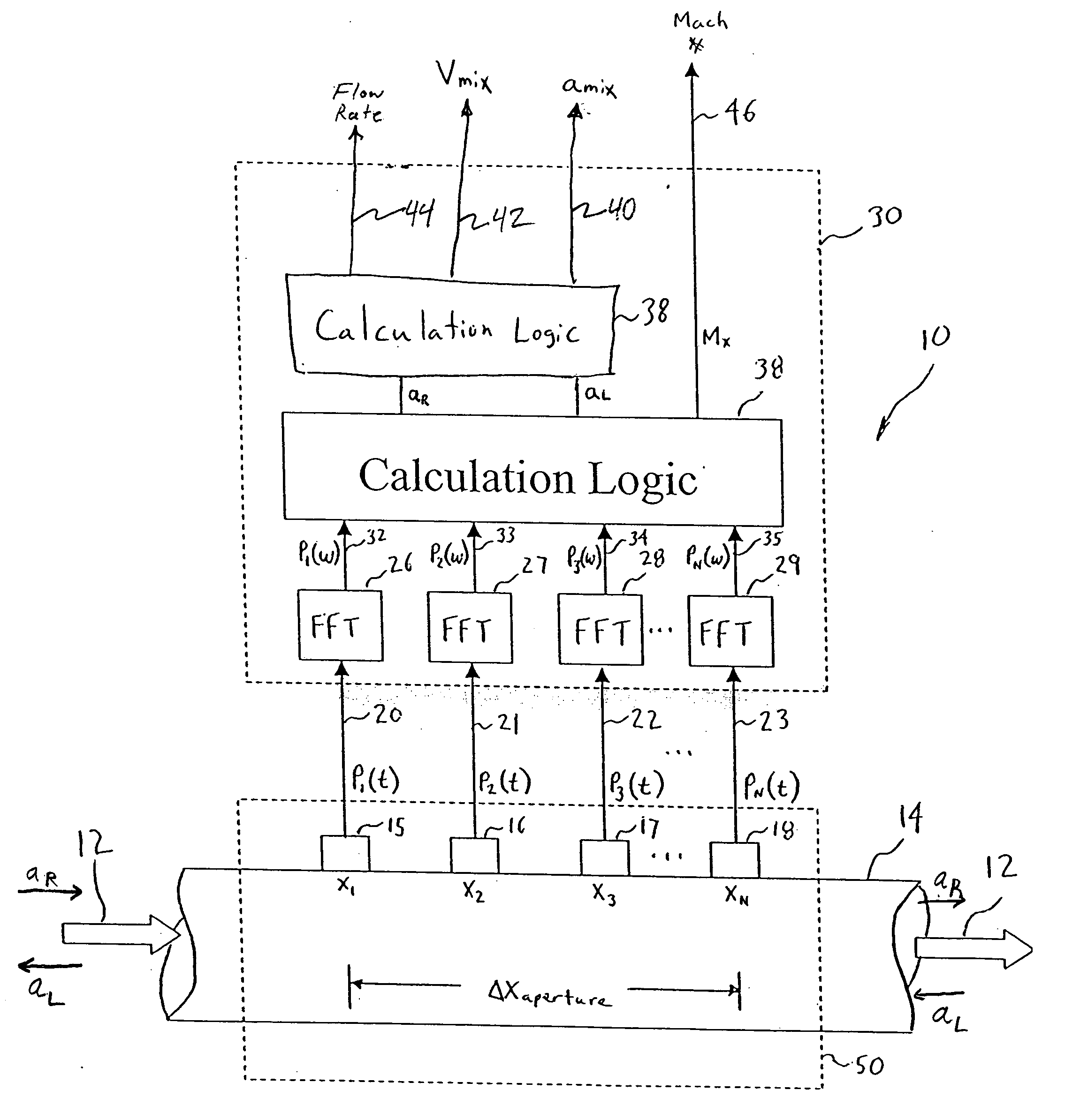
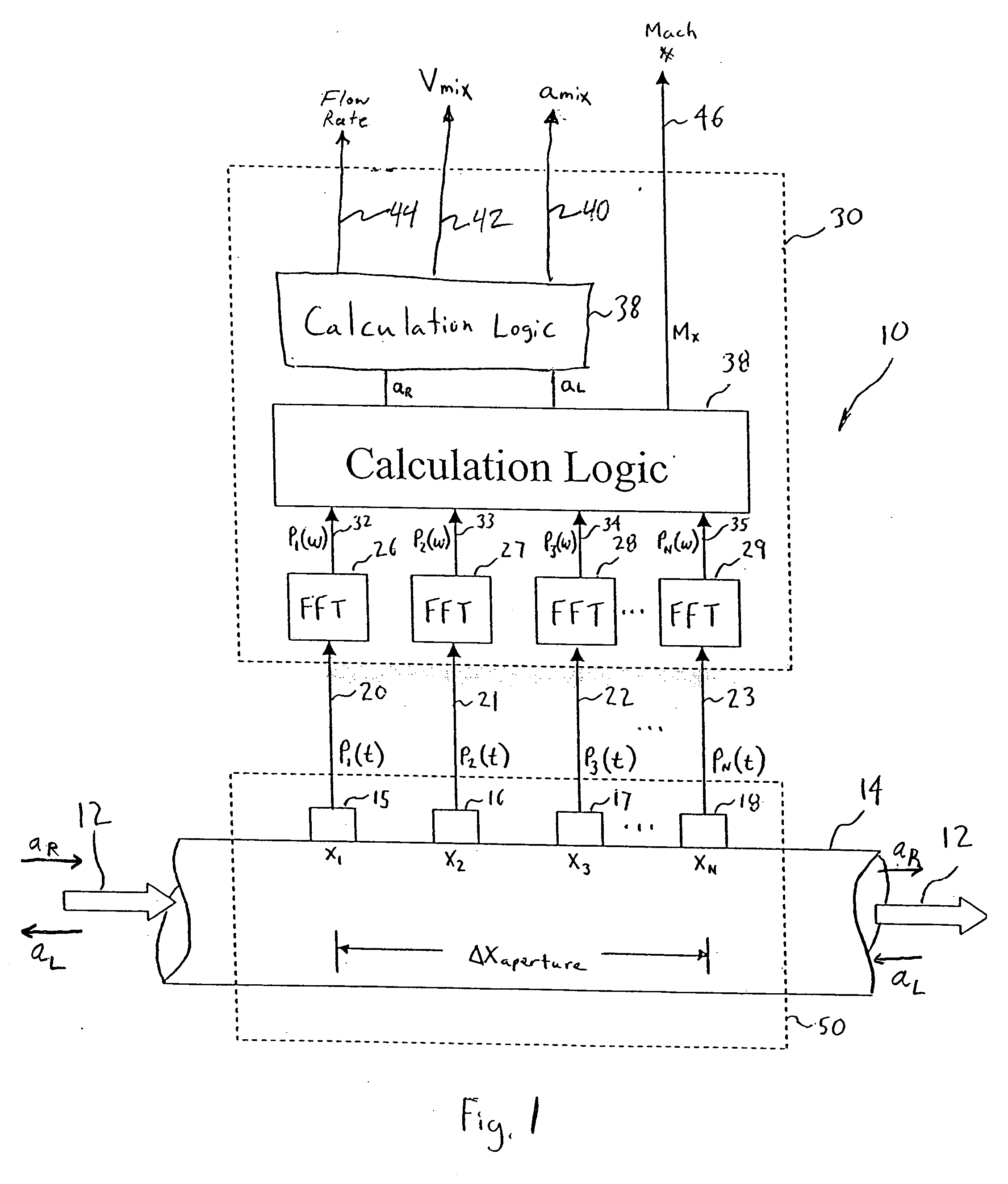
An apparatus 10 and method is provided that includes a spatial array of unsteady pressure sensors 15-18 placed at predetermined axial locations x1-xN disposed axially along a pipe 14 for measuring the velocity and volumetric flow rate of a single phase or multi-phase fluid 12 having a non-negligible axial Mach number flowing in the pipe 14. The pressure sensors 15-18 provide acoustic pressure signals P1(t)-PN(t) to a signal processing unit 30 which determines the speed of sound propagating with and against the flow of the fluid 12 in the pipe 14 using acoustic spatial array signal processing techniques. The apparatus, responsive to the measured speed of sound propagating with and against the flow of the fluid, determines the velocity and the flow rate of the fluid propagating through the pipe.

Description


Claims


Application Information

Patent Timeline
Owner EXPRO METERS
Why Eureka
Try Eureka