Layout structure of driving device for vehicle
a technology of driving device and layout structure, which is applied in vehicle maintenance, vehicle cleaning, jet propulsion mounting, etc., can solve the problems of limiting the compactness of the engine, not providing the above-described further moved-back engine layout, and large yaw inertia moment, etc., to achieve the effect of improving the facility
- Summary
- Abstract
- Description
- Claims
- Application Information
AI Technical Summary
Benefits of technology
Problems solved by technology
Method used
Image

Examples
embodiment 1
[0075] Embodiment 1
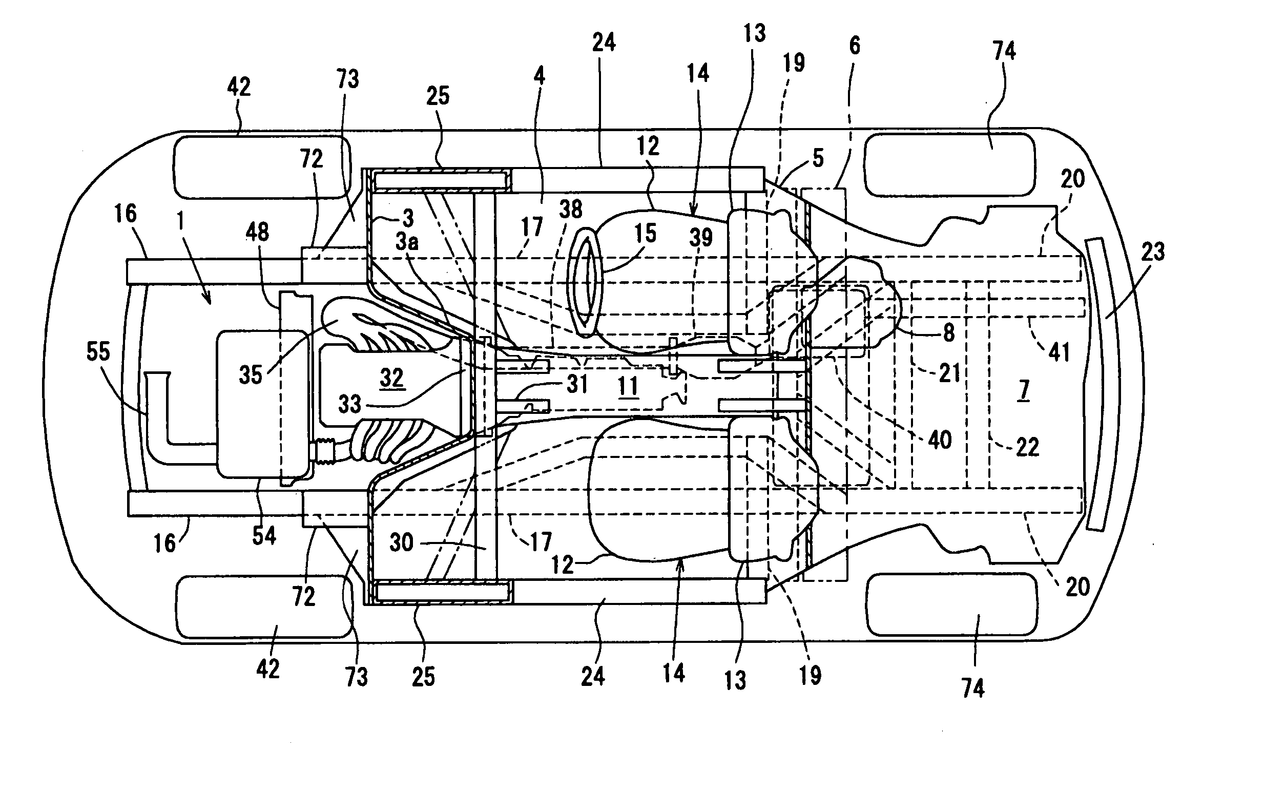
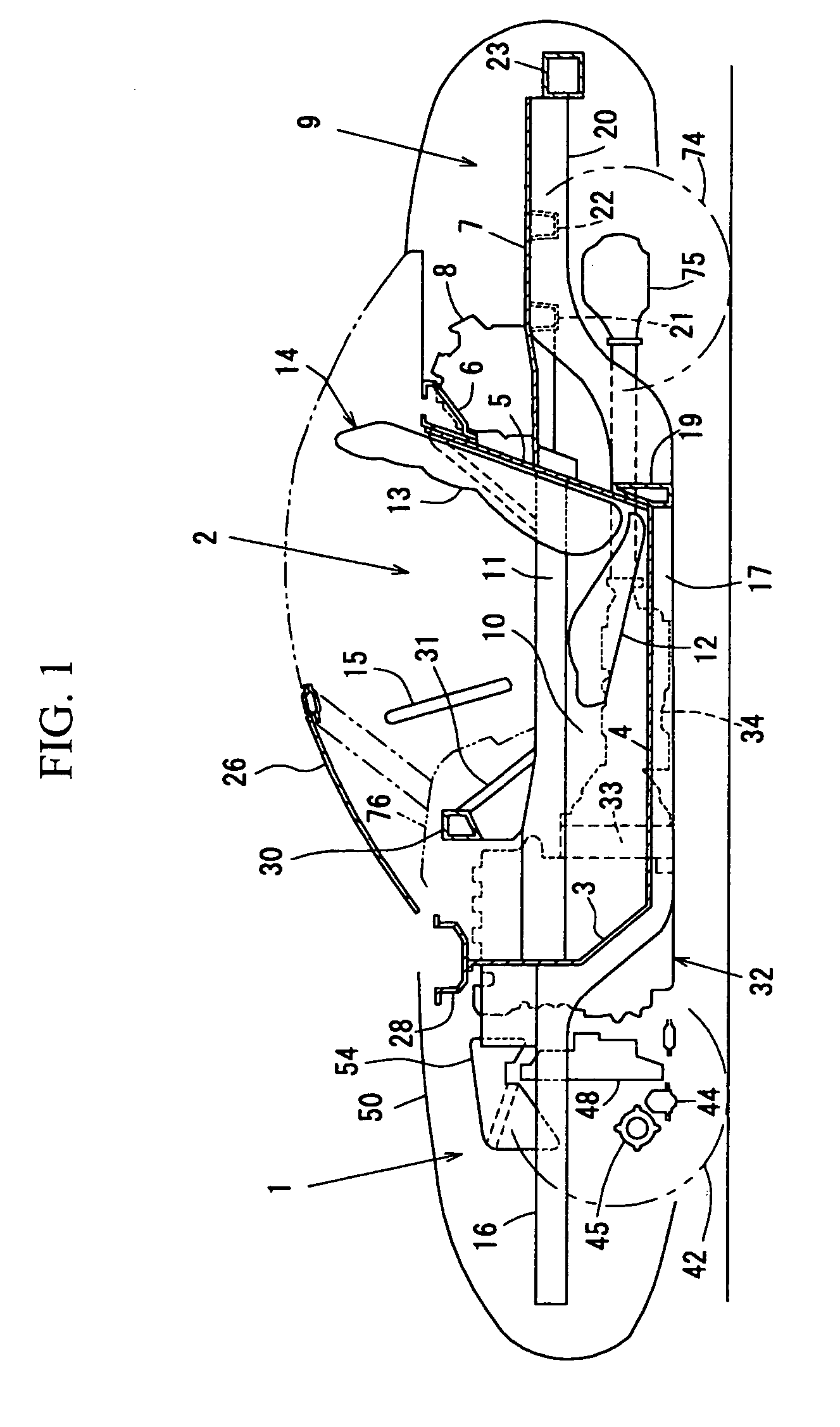
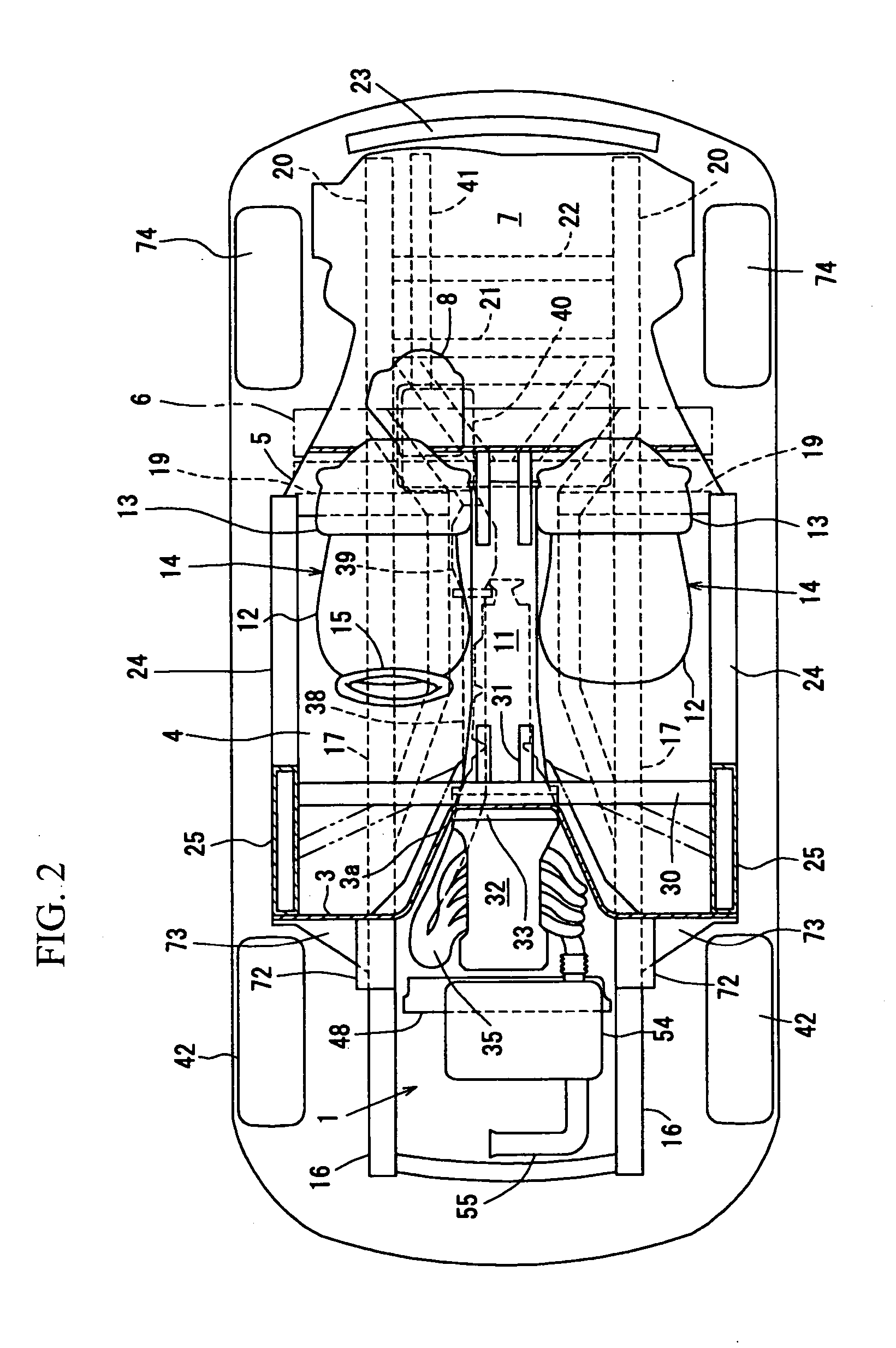
[0076] The first embodiment of the present invention will be described in detail referring to FIGS. 1 through 9. The figures show a layout structure of a driving device for a vehicle. In a side view, FIG. 1 and a plan view, FIG. 2, an engine room 1 is separated by a dash lower panel 3 (dash panel) from a passenger compartment 2 in a longitudinal direction of the vehicle.
[0077] A floor panel 4 is subsequently connected to a lower end portion of the dash lower panel 3 to extend backward in a substantially horizontal direction. A bulkhead 5 is provided so as to rise up slantingly from a rear portion of the floor panel 4, at a back face of an upper end portion of which there is provided a rear cowl portion 6 extending in a width direction of the vehicle. Herein, the rear bulkhead 5 is a panel member which separates the passenger compartment 2 from a rear part compartment.
[0078] Further, a rear floor 7 is provided to extend backward from a middle portion of the bulkh...
embodiment 2
[0121] Embodiment 2
[0122] The second embodiment of the present invention will be described. This embodiment comprises a structure in which a heat exchanger is interposed between a front end of the driving device and an axle of the front wheel. This structure is shown in FIGS. 10 through 19, and hereinafter it will be described in detail referring to these drawings.
[0123] Herein, the same structure as the above-described first embodiment is illustrated in the same way, having the same reference numerals, in respective figures which correspond to those of the first embodiment, whose detailed descriptions will be omitted hereinafter. (FIGS. 10, 11, 12, 14 and 16 correspond respectively to FIG. 1, 5, 2, 3 and 4)
[0124] As shown in FIGS. 14 and 15, the cooling unit 48 (the unit including a radiator and a fan) is supported on the suspension cross member 44 through the bracket 47, and the air conditioning condenser, namely the so-called cooler condenser 49 is located in front of the cooli...
PUM
 Abstract
Description
Claims
Application Information
 - R&D Engineer
- R&D Manager
- IP Professional
- Industry Leading Data Capabilities
- Powerful AI technology
- Patent DNA Extraction
Browse by: Latest US Patents, China's latest patents, Technical Efficacy Thesaurus, Application Domain, Technology Topic.
© 2024 PatSnap. All rights reserved.Legal|Privacy policy|Modern Slavery Act Transparency Statement|Sitemap