Extruding implement structure

a technology of implements and implements, applied in the direction of instruments, liquid transfer devices, volume meters, etc., can solve the problems of inconvenience and waste, large loading moments, and very dangerous operation

Inactive Publication Date: 2005-01-13
TSENG YU CHUN
View PDF9 Cites 11 Cited by
  • Summary
  • Abstract
  • Description
  • Claims
  • Application Information

AI Technical Summary

Problems solved by technology

The handle of such extruding implement is vertical to the silicon gel can, not only wasting the space for the overall packaging volume, but since the silicon gel can is very heavy, the base 1 is made of metal, and the handle is disposed o

Method used


Image

  • Extruding implement structure
  • Extruding implement structure
  • Extruding implement structure

Examples


Embodiment Construction

[0013] Referring to FIG. 3, the extruding implement of a preferred embodiment of the present invention comprises: a base 5; a front blocking base 51 disposed at the front end; a rear base 52 disposed at the rear end; a silicon gel can 6 accommodated between the front block base 51 and the rear base 52, such that a conical nozzle 61 of the silicon gel can 6 protrudes to the front of the front blocking base 51; a push rod 7 passing through the rear base 52, and one end of the push rod 7 extending into the base 5 and its front end having a pressing disc 53 to press a movable rear cover 62 in the silicon gel can 6; the push rod 7 in a hollow hole 53 of the rear base 52 being pivotally coupled to a first elastic member 71 and a first latch plate 72; the push rod 7 outside the rear base 52 has a latch member 73 between the rear base 52 and the second latch plate 74, and the latch member 73 having an appropriate latching force to latch the push rod 7, and requiring an appropriate external ...


PUM


Abstract

The extruding implement structure of the present invention comprises a handle pivotally connected to a rear base and disposed on one side of the base, and is substantially parallel to the base or in an aslant position, using a first resisting arm to press against a pushing member of a first exerting arm pivotally coupled to a rear base, and the pushing member uses a second resisting arm on the other end of the pivotal point to press against the first latch plate and drive the push rod to push and press against the silicon gel can for the gel injection. A latch member is disposed between the outside of the rear base and the second latch plate such that the silicon gel will not keep on squeezing the silicon gel after the operation is stopped.

Description

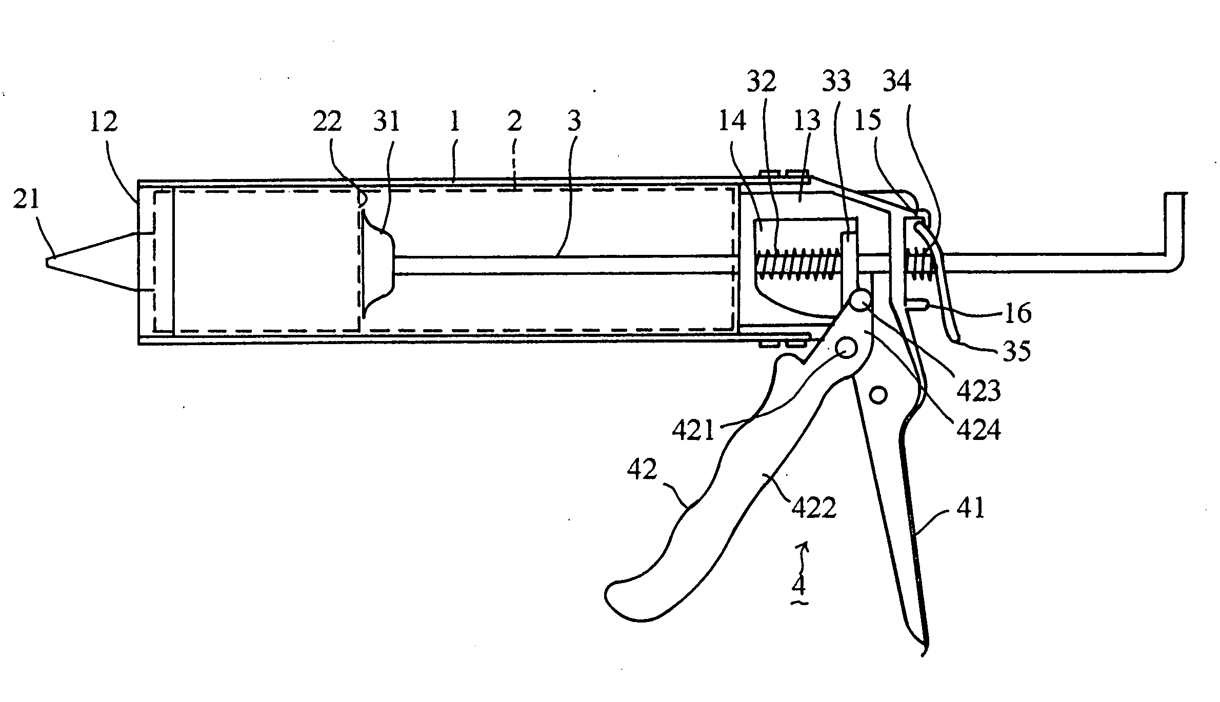
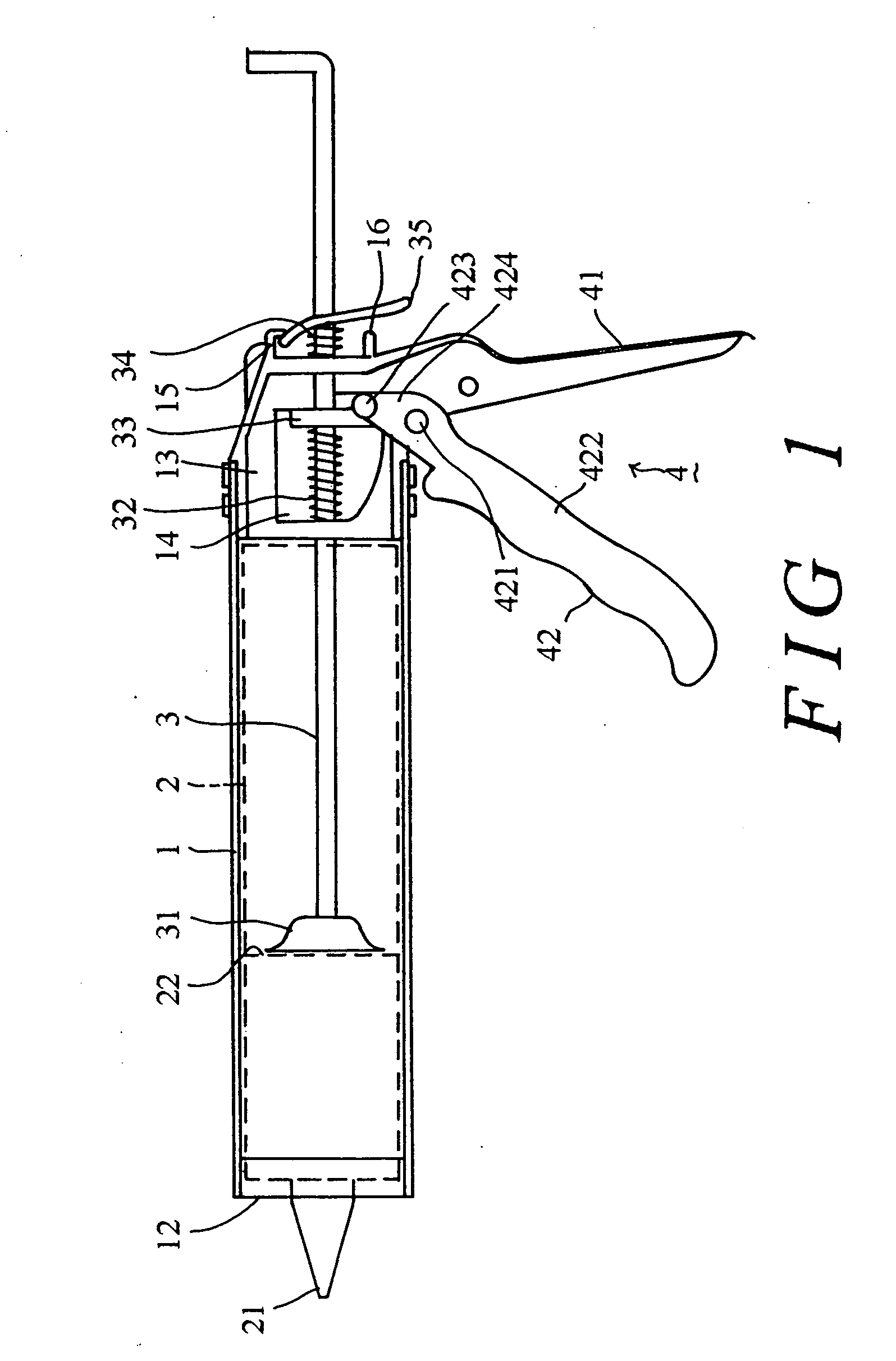
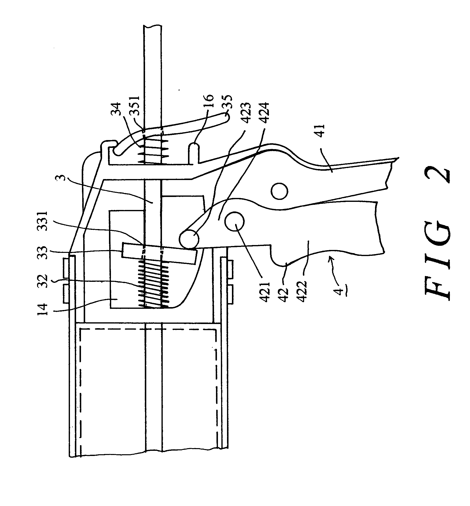
BACKGROUND OF THE INVENTION [0001] 1. Field of the Invention [0002] This invention relates to an extruding implement structure, more particularly to an extruding implement structure used for squeezing the contents contained in a can featuring its easy application and easy control, and saving the volume of packaging materials. [0003] 2. Description of the Related Art [0004] In general, a silicon gel which is common in construction, decoration, or DIY construction in family, is generally used for waterproof sealing, and an extruding implement is generally used for squeezing the silicon gel. Please refer to FIG. 1 for a general extruding implement structure, which comprises: a base 1; a front blocking base 12 disposed at the front end; a rear base 13 disposed at the rear end; a silicon gel can 2 accommodated in the base 1 such that a conical nozzle 21 of the silicon can 2 being protruded to the front of the front blocking base 12; a push rod 3 passing through the rear base 13, having a...

Claims


Application Information

Patent Timeline
IPC IPC(8): B05C17/01
CPCB05C17/01
Inventor TSENG, YU-CHUN
Owner TSENG YU CHUN
Why Eureka
Try Eureka