Stir-friction hot working control system

a technology of stirfriction and control system, which is applied in the direction of metal-working equipment, welding equipment, manufacturing tools, etc., can solve the problems of inability to make small adjustments in the depth of penetration, inconvenient to change the penetration depth, and subject to error

Inactive Publication Date: 2005-01-13
ADAMS GLYNN PAUL +3
View PDF10 Cites 29 Cited by
  • Summary
  • Abstract
  • Description
  • Claims
  • Application Information

AI Technical Summary

Problems solved by technology

The roller arrangement 26 for controlling the depth of penetration of the pin tool during stir-friction welding or hot working is effective, but the roller apparatus makes it inconvenient to change the penetration depth from one workpiece to another, and it is not possible to make small adjustments in the depth of penetration during a weld or hot-working procedure.
This technique provides easy change of depth of penetration, by simply adjusting the signal representing the desired penetration, but is subject to error due to the large number of dimensions which must be added and subtracted in order to arrive at the calculated value, and because of axial position variation or changes due to slack in the spindle bearings, and similar tolerances.

Method used


Image

  • Stir-friction hot working control system
  • Stir-friction hot working control system
  • Stir-friction hot working control system

Examples


Embodiment Construction

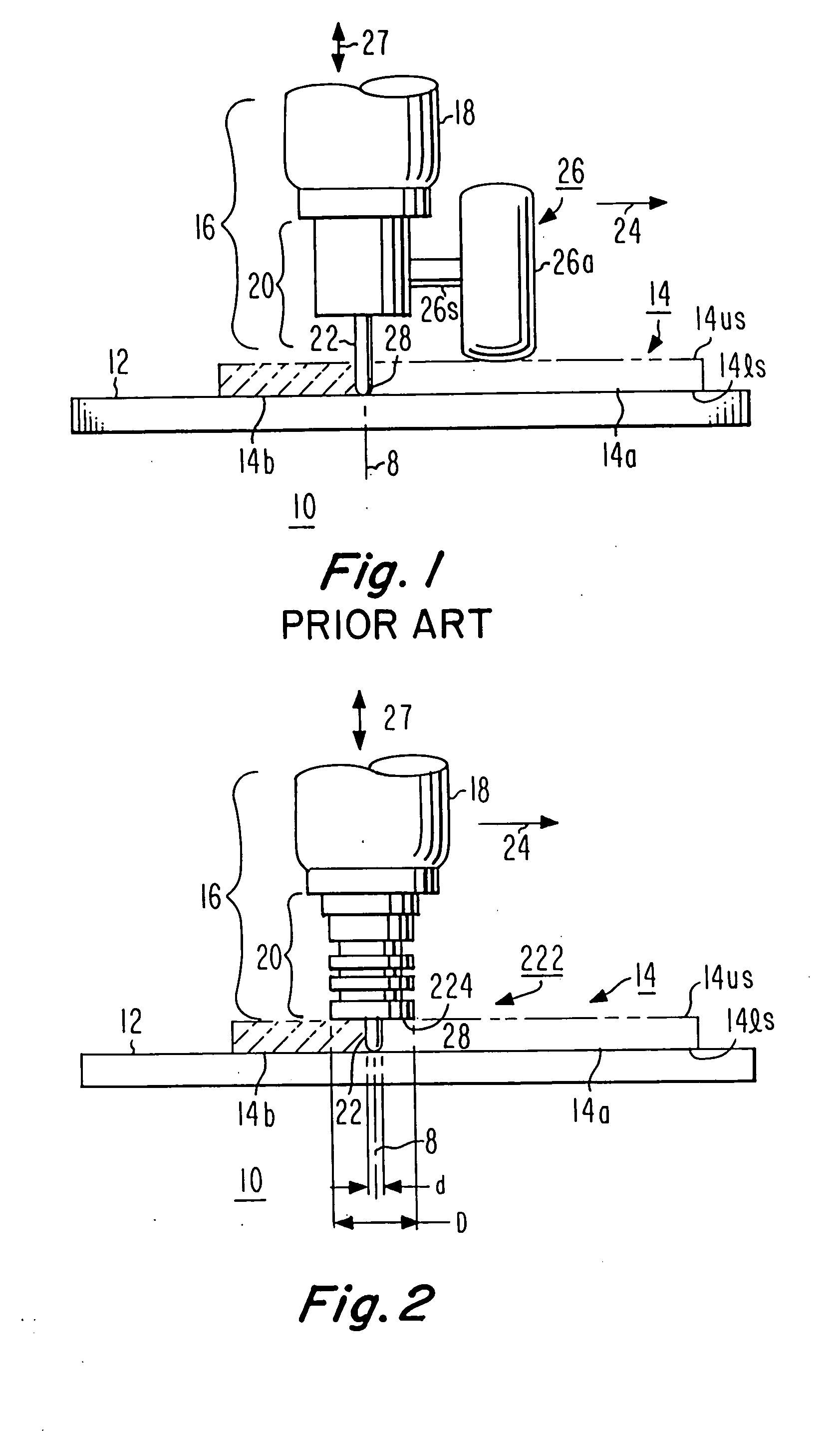
[0020]FIG. 2 is a simplified diagram, similar to FIG. 1, showing a pin tool 222 which includes a ligament 22 having a diameter d at locations away from the rounded tip, and also including a shoulder portion 224 having a larger diameter D than the diameter d of the ligament portion 22. As illustrated in FIG. 2, the shoulder portion 224 rides on the upper surface 14us of the workpiece 14 during operation, and the length of the ligament 22 in relation to the intended depth of hot-working or welding is selected to approximately equal the pin-tip-to-shoulder distance. Thus, the distance between the pin tip 28 and shoulder 224 in FIG. 2 is about equal to the depth of hot-working or welding.

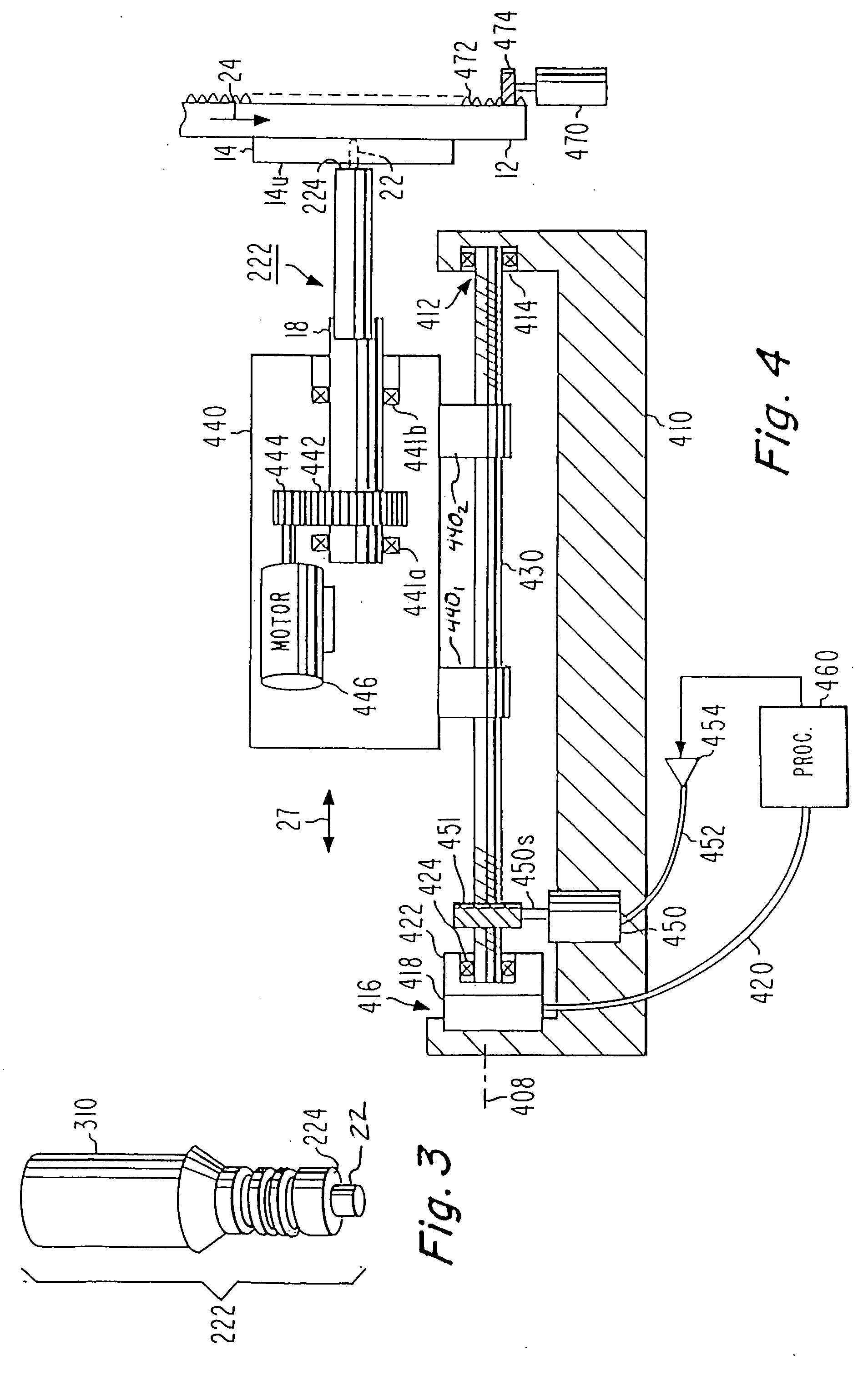
[0021]FIG. 3 illustrates the pin tool 222 of FIG. 2 separate from the spindle 18. As illustrated in FIG. 3, the pin tool 222 includes a shank 310 in addition to the shoulder portion 224 and pin or ligament 22. The grooves cut into the pin support in FIG. 3 are for ______.

[0022]FIG. 4 is a simplified d...


PUM

PropertyMeasurementUnit
plunge depthaaaaaaaaaa
frictionaaaaaaaaaa
depthaaaaaaaaaa

Abstract

A stir-friction hot-working or welding arrangement uses a pin tool having a ligament 22 and a shoulder 224. The force required for incremental penetration increases markedly when the shoulder is reached. A control system for maintaining a set penetration depth includes a load cell for measuring force or pressure applied to the pin tool. The control system compares a reference signal representing the desired force with the actual force from the load cell, to produce an error signal which controls the penetration force, thereby tending to maintain a desired penetration depth. In a particular embodiment, the reference signal ramps up from a low or zero value at turn-on, to reduce forces applied upon initial penetration. In another embodiment, position signals are used to control a modulator or multiplier, which changes the error signal applied at certain positions of penetration, or at certain velocities of penetration.

Description

FIELD OF THE INVENTION [0001] This invention relates to control arrangements for stir-friction welders, and more particularly to automatic positioning systems for stir-friction welders. BACKGROUND OF THE INVENTION [0002]FIG. 1 is a simplified illustration of a prior-art stir-friction welding arrangement 10. In FIG. 1, an anvil 12 supports a flat workpiece 14, illustrated in phantom to make other portions of the arrangement more obvious. A friction-stir pin tool and spindle arrangement designated generally as 16 includes a spindle 18 which rotates about its axis 8, carrying with it a pin tool or ligament holding arrangement 20. The pin tool itself includes an elongated pin or ligament 22, which also rotates in consonance with the rotating spindle 18. As the spindle 18, holder 20, and pin tool 22 rotate, a relative motion is introduced between the anvil 12 (carrying the workpiece 14) and the spindle-and-pin-tool arrangement 16. The motion is represented by an arrow 24, which suggests ...

Claims


Application Information

Patent Timeline
Patent Type & Authority Applications(United States)
IPC IPC(8): B23K20/12
CPCB23K20/123
Inventor ADAMS, GLYNN PAULLOFTUS, ZACHARY SEAN SAMUELMCCORMAC, JOSEPH NATHANVENABLE, RICHARD ALLEN
Owner ADAMS GLYNN PAUL
Why Eureka
Try Eureka