Monitor improved in a tilting and combining structure

a technology of combining structure and monitor, which is applied in the field of monitors, can solve the problems of inability to install the monitor on an inclined plane such as a wall, the arm stand cannot be removed, and the main body angle cannot be adjusted, so as to achieve the effect of convenient installation

Inactive Publication Date: 2005-01-13
SAMSUNG ELECTRONICS CO LTD
View PDF99 Cites 8 Cited by
  • Summary
  • Abstract
  • Description
  • Claims
  • Application Information

AI Technical Summary

Benefits of technology

[0011] Accordingly, it is an object of the present invention to provide a monitor, in which a base member is installed onto an inclined plane such as a wall, an arm stand, etc., and more particularly, to provide a monitor which is easily installed onto various arm stands according to VESA standards.
[0012] Another object of the present invention is to provide a monitor which properly adjusts a tilting angle of a main body against a base member, and decrease costs to keep and carry the monitor by minimizing the packing volume thereof.
[0038] According to an aspect of the invention, the first hinge pin is placed a first torsion spring having a first end coupled to the one side of the lower end part of the link member and a second end coupled to the first fixing bracket, and elastically acting in an opposite direction to a downward rotation of the link member against the base member. Thus, the first torsion spring allows the link member to be positioned in place.

Problems solved by technology

Therefore, with the conventional monitor, it is inconvenient to adjust an angle of the main body 202 as necessary.
However, in the conventional monitor, because the base member 210 must be laid on the horizontal plane, it is impossible to install the monitor onto an inclined plane such as a wall, the arm stand, etc.
Thus, a packing volume of the monitor cannot be decreased, thereby increasing costs to keep and carry the monitor.
Furthermore, if regulations regarding the angle adjustment of the main body 202 are different in various nations, it is difficult to adaptively meet regulation requirements for the angle adjustment.

Method used


Image

  • Monitor improved in a tilting and combining structure
  • Monitor improved in a tilting and combining structure
  • Monitor improved in a tilting and combining structure

Examples


Embodiment Construction

[0070] Reference will now be made in detail to the present preferred embodiments of the present invention, examples of which are illustrated in the accompanying drawings, wherein like reference numerals refer to like elements throughout.

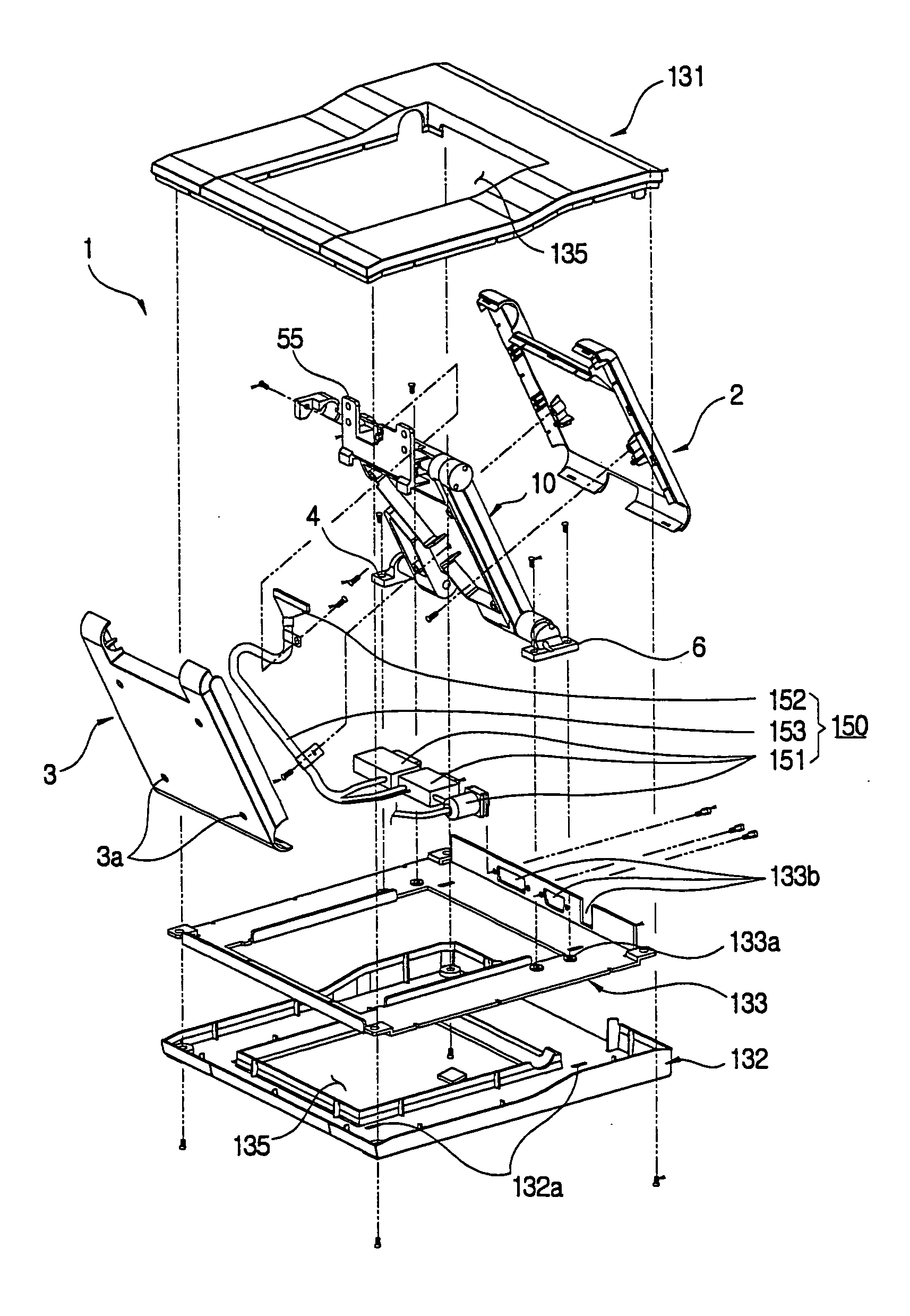
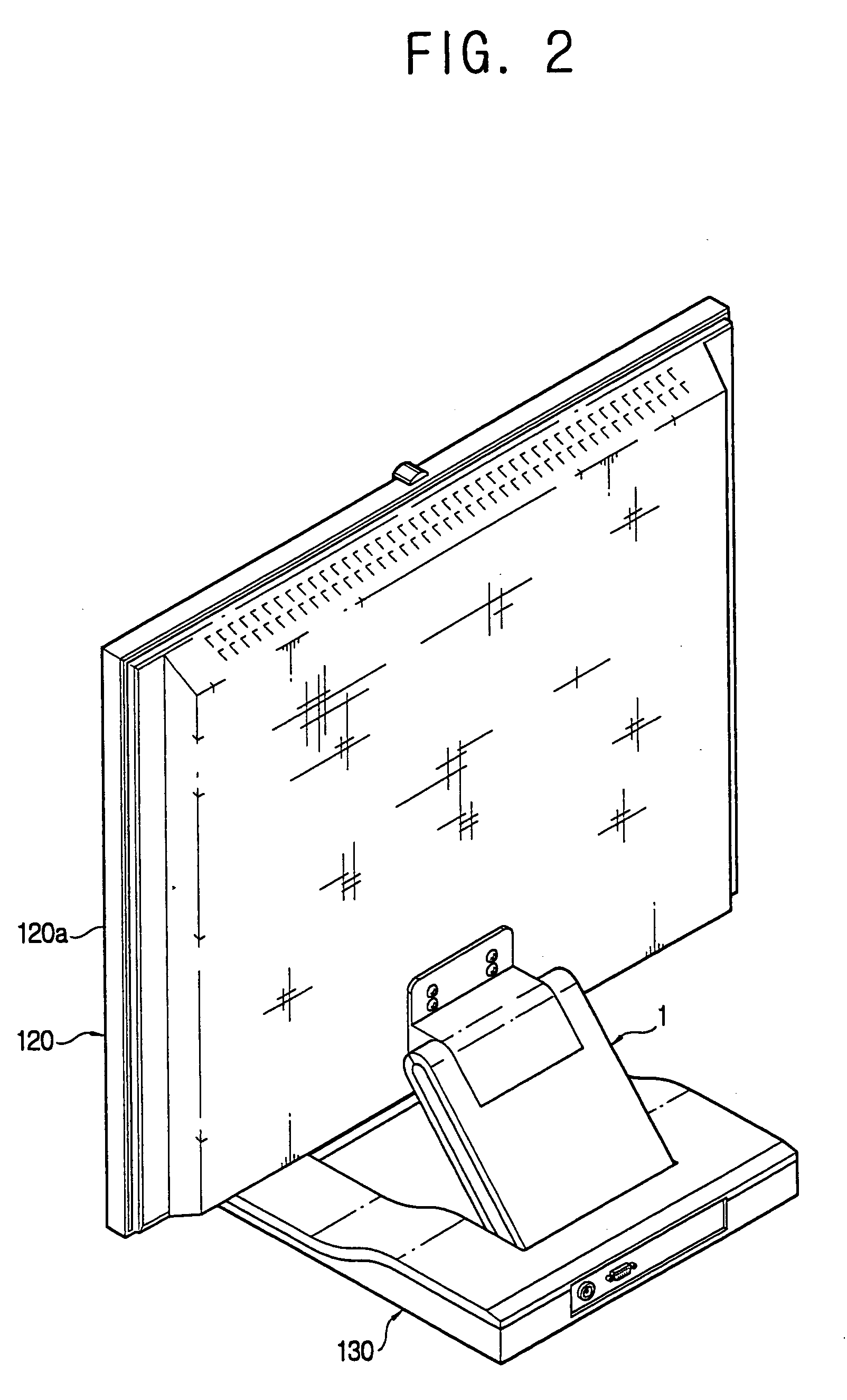
[0071] As shown in FIGS. 2 and 3, a monitor according to an embodiment of the present invention includes a base member 130 laid on a predetermined horizontal plane and a monitor main body 120 having a screen 120a to display a picture. The monitor also includes a link assembly 1 linking the base member 130 with the monitor main body 120 and a base bracket 140 having a first side combined to a rear of the base member 130 and a second side combined to an inclined plane including a vertical plane such as a wall, an arm stand, etc.

[0072] The base bracket 140 includes a plurality of hooks 141 provided in the first side combined to the rear of the base member 130, a plurality of first combining holes 143 to combine with the inclined plane such as a wall, ...


PUM


Abstract

A monitor has a monitor main body and a base member to support the monitor main body. The monitor includes a link member disposed between the monitor main body and the base member, a base hinge coupling the link member, which is to be rotated within a predetermined angle against the base member, with the base member, and a monitor hinge coupling the monitor main body, which is to be rotated against the link member, with the link member. The monitor includes an auxiliary link member to link the rotation of the link member against the base member with the rotation of monitor main body, and a base bracket combined to the base member to allow the base member to be installed on an inclined plane.

Description

CROSS-REFERENCE TO RELATED APPLICATIONS [0001] This application is a divisional of U.S. application Ser. No. 10 / 295,831, now pending. This application also claims the benefit of Korean Application No. 2001-71860, filed Nov. 19, 2001, Application No. 2002-27683, filed May 20, 2002, and Application No. 2002-56429 filed Sep. 17, 2002, in the Korean Industrial Property Office, the disclosures of which are incorporated herein by reference.BACKGROUND OF THE INVENTION [0002] 1. Field of the Invention [0003] The present invention relates in general to a monitor, and more particularly, to a monitor improved in tilting structure of the monitor against a base member, and improved in combining structure of the base member and an inclined plane. [0004] 2. Description of the Related Art [0005] As shown in FIG. 1, a conventional monitor includes a base member 201 laid on a horizontal plane, a monitor main body 202 to display a picture thereon, and a link member 210 to link the base member 201 with...

Claims


Application Information

Patent Timeline
Patent Type & Authority Applications(United States)
IPC IPC(8): F16C11/10F16M11/10F16M13/02G09F9/00H04N5/64H05K5/02
CPCF16M11/046F16M11/048F16M11/10F16M13/02Y10S248/923F16M2200/063F16M2200/08Y10T16/540345Y10S248/919F16M2200/041
Inventor JUNG, HYUN-JUNJEONG, JUN-SOO
Owner SAMSUNG ELECTRONICS CO LTD
Why Eureka
Try Eureka