Peer-to-peer network heartbeat server and associated methods

a peer-to-peer network and heartbeat server technology, applied in the field of computer networks, can solve the problems of no simple or efficient method to count and identify, no simple or efficient method the crawler will take exponentially more time to crawl the network, so as to achieve the effect of not compromising speed and efficiency, and less bandwidth

Inactive Publication Date: 2005-01-13
FREE PEERS
View PDF10 Cites 124 Cited by
  • Summary
  • Abstract
  • Description
  • Claims
  • Application Information

AI Technical Summary

Benefits of technology

[0045] It is an additional object of the present invention to provide a method for controlling the configuration of nodes in a peer-to-peer network that consumes less bandwidth and CPU resources than known methods.
[0046] It is an additional object of the present invention to provide a method for controlling the configuration of nodes in a peer-to-peer network that does not require a central server to be contacted by each node.
[0047] It is an additional object of the present invention to provide a method for controlling the configuration of nodes in a peer-to-peer network whose speed and efficiency is not compromised by network growth.
[0048] It is an additional object of the present invention to provide a method for controlli...

Problems solved by technology

Existing peer-to-peer network architectures suffer from significant drawbacks which relate directly to their decentralized nature.
One disadvantage of existing peer-to-peer network architectures is that there is no simple or efficient method to count and identify the number of nodes connected to the network at any one time.
In addition, a crawler will take exponentially more time to crawl the network as the network grows.
This reduces the accuracy of its results because the longer it takes to crawl the network the more likely it is that nodes will have left or joined the network by the time the results are tallied.
The central server model suffers from incurring an ever increasing bandwidth use penalty as the network grows, even in situations in which the central server is offline.
There is nothing to prevent this increasing bandwi...

Method used


Image

  • Peer-to-peer network heartbeat server and associated methods
  • Peer-to-peer network heartbeat server and associated methods
  • Peer-to-peer network heartbeat server and associated methods

Examples


Embodiment Construction

[0056] While the present invention will be described more fully hereinafter with reference to the accompanying drawings, in which a preferred embodiment of the present invention is shown, it is to be understood at the outset of the description which follows that persons of skill in the appropriate arts may modify the invention herein described while still achieving the favorable results of this invention. Accordingly, the description which follows is to be understood as being a broad, teaching disclosure directed to persons of skill in the appropriate arts, and not as limiting upon the present invention.

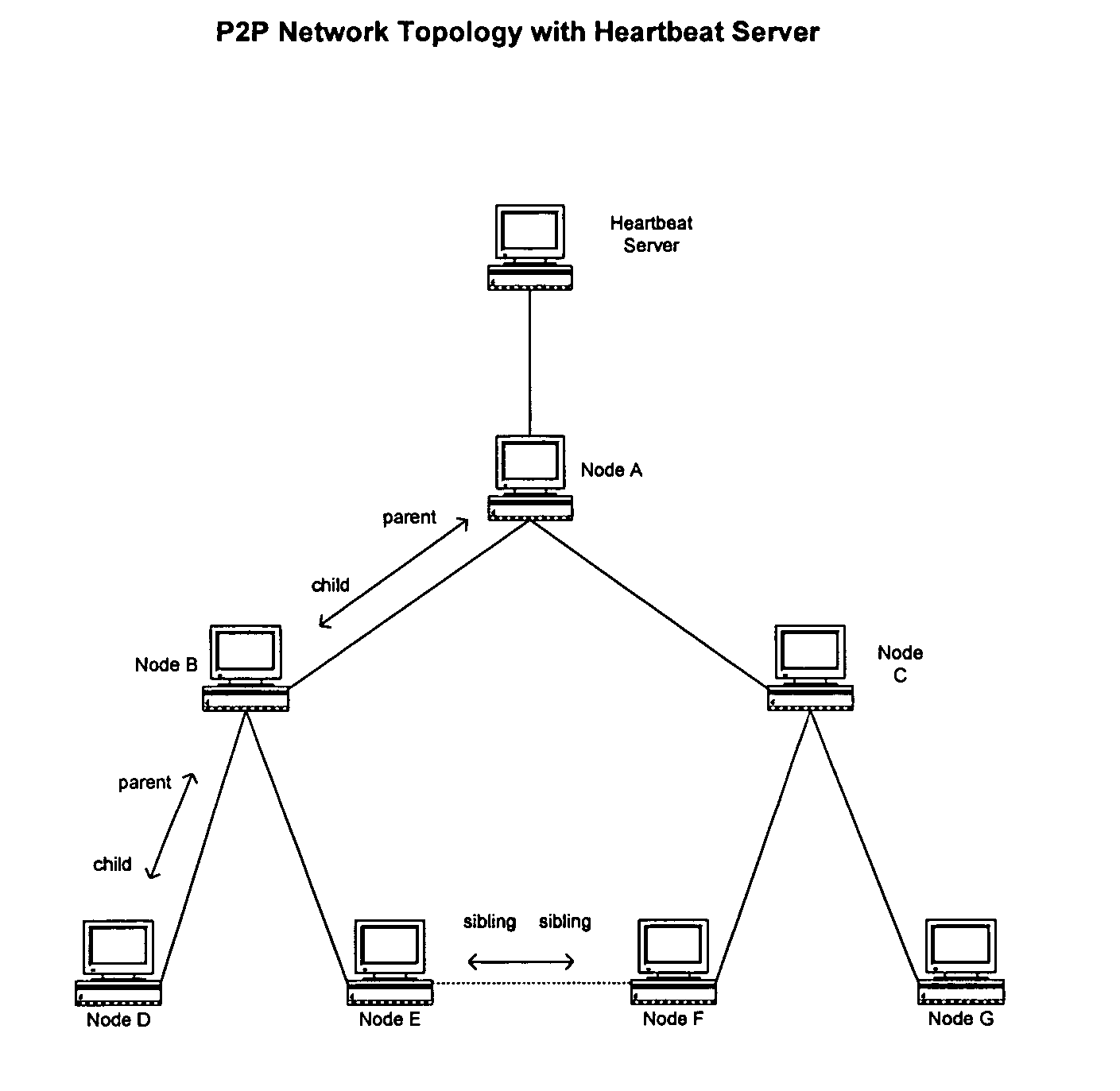
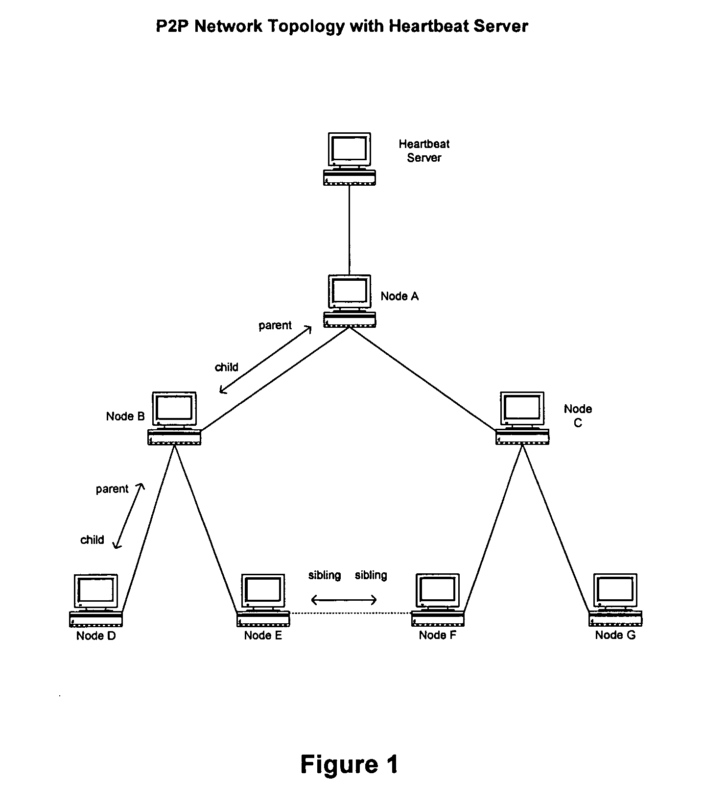
[0057] The following describes a specific implementation, operation and use of a heartbeat server, as embodied in a Gnutella peer-to-peer network.

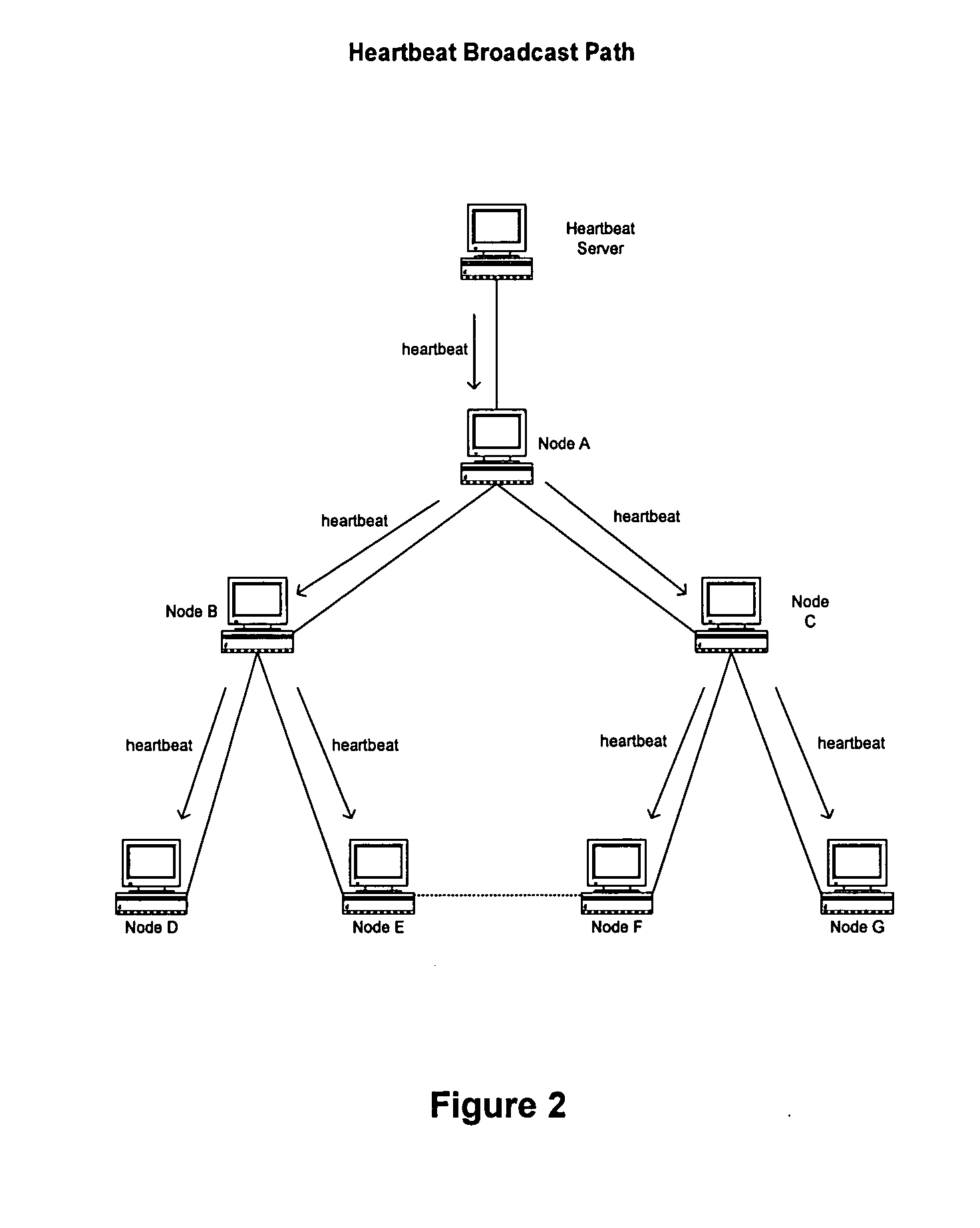
[0058] A heartbeat server is a node on the network which forwards heartbeat messages to its directly connected neighbors. These neighbors forward the message to their neighbors and so on, in the manner of a traditional peer-to-peer query ...


PUM


Abstract

A self-defined, automatically-configured hierarchical peer-to-peer networking method is disclosed. Network hierarchy is determined by the proximity (quantified as lower latency) of nodes in the network to a predetermined heartbeat server node. Nodes in closer proximity to the server node are considered parent of nodes in farther proximity. Nodes in equal proximity to the server node are considered siblings to each other. The disclosed network has a loop-free connectivity topology where a parent node may have multiple child nodes but does not share any child nodes with other parents.

Description

CLAIM OF PRIORITY [0001] This application is a non-provisional of U.S. patent application Ser. No. 60 / 484,141, filed on Jul. 1, 2003, the contents of which are incorporated herein by reference.TECHNICAL FIELD [0002] This invention relates generally to computer networks, and specifically to structure, operation, configuration and use of a novel peer-to-peer network (hereinafter “P2P network” or “peer-to-peer network” interchangeably). A peer-to-peer network is defined generally as a type of decentralized multi-node digital computer network in which all of the nodes have substantially equivalent capabilities and responsibilities. peer-to-peer networks may be contrasted with client / server architectures, in which some nodes are dedicated to serving (i.e., the servers) the remaining nodes (i.e., the clients.) BACKGROUND OF THE INVENTION [0003] This invention relates specifically to the implementation of a novel peer-to-peer network, and methods associated therewith, for use in file searc...

Claims


Application Information

Patent Timeline
IPC IPC(8): H04L12/24H04L29/06H04L29/08
CPCH04L29/06H04L41/12H04L69/329H04L67/1089H04L67/104H04L9/40
Inventor FALCO, VINCENTNICPONSKI, DAVEDARWIN, SAM
Owner FREE PEERS
Why Eureka
Try Eureka