Indicating instrument for vehicle

Active Publication Date: 2005-01-20
DENSO CORP
View PDF6 Cites 16 Cited by
  • Summary
  • Abstract
  • Description
  • Claims
  • Application Information

AI Technical Summary

Benefits of technology

[0014] In the above structure of the present invention, the printed circuit board is divided into two boards: a design board where the movement and light source are mounted; and a control board where the control circuit is mounted. Here, in designing the design board, man power for decreasing the arisin

Problems solved by technology

Namely, a control circuit generates the voltage in pulse, so that so-called electrical noise is radiated and

Method used


Image

  • Indicating instrument for vehicle
  • Indicating instrument for vehicle
  • Indicating instrument for vehicle

Examples


Example

First Embodiment

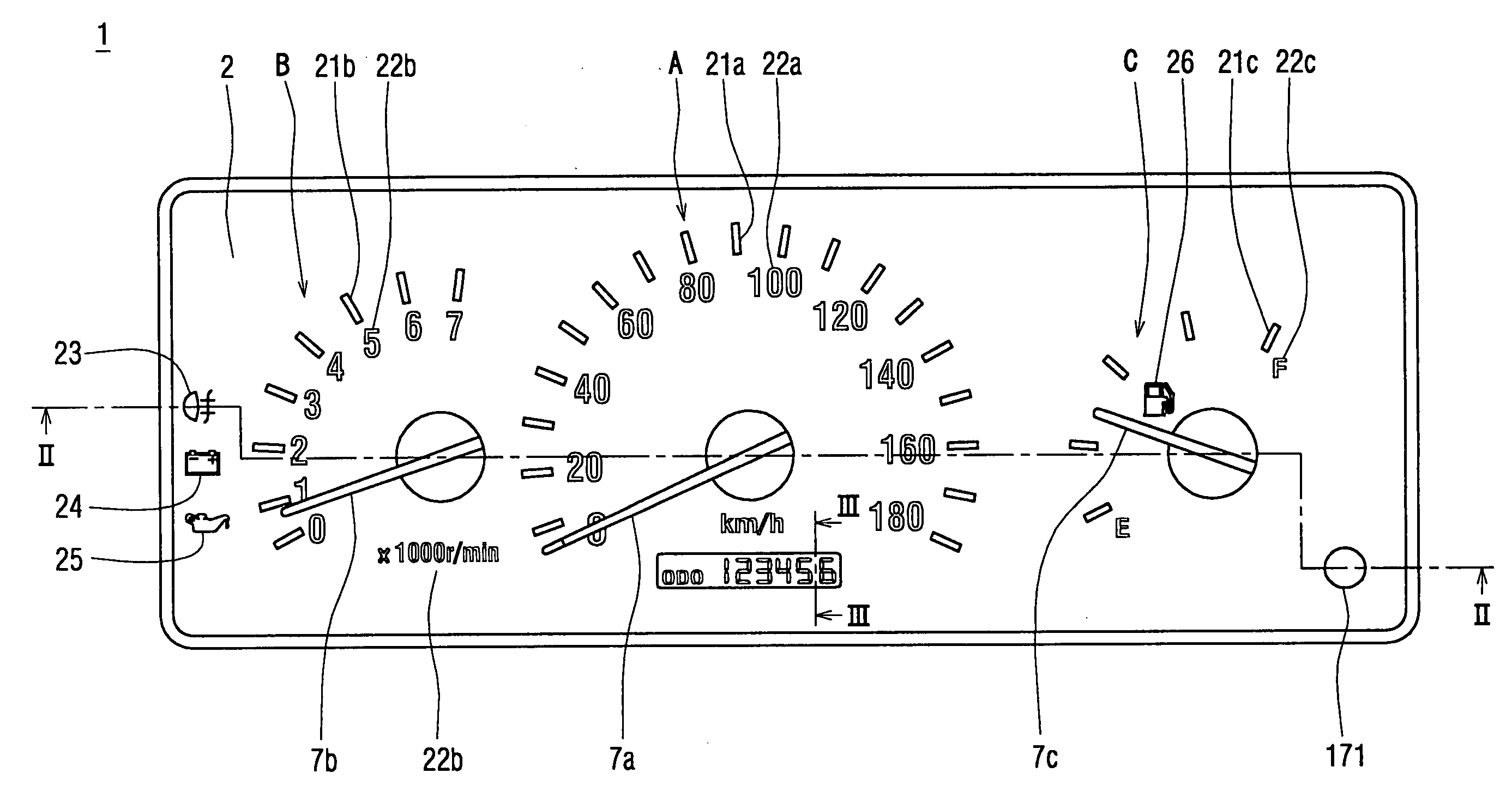
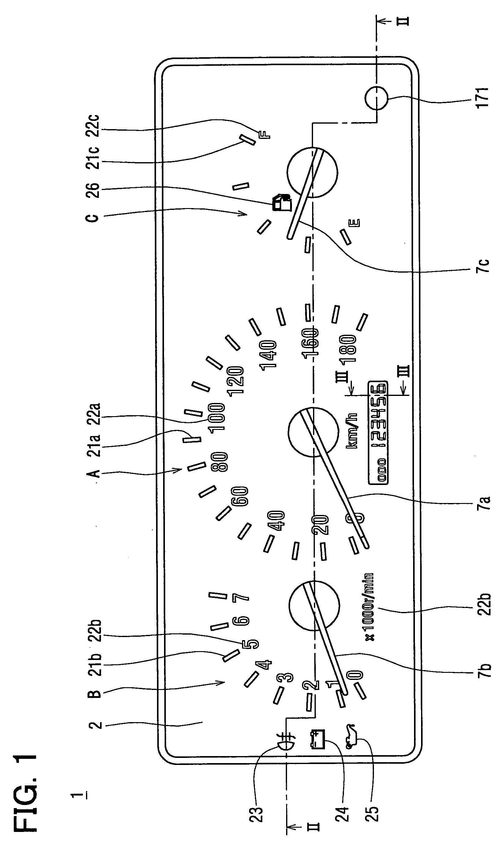
[0027] A combination meter 1 displays various information relating to a relevant vehicle and is disposed in such a manner that a driver seated in the front driver seat can see the combination meter 1.

[0028] The combination meter 1 primarily includes, in its dial plate 2, indicating instruments of a speedometer A, tachometer B, and fuel meter C; and display portions of a fog lamp indicator 23, voltage indicator 24, and oil pressure indicator 25, as shown in FIG. 1. Hereinafter, “front” or “forward” of the combination meter 1 is the side, surface, space, etc. of the combination meter 1 that faces the driver seat, while “back” or “backward” of the combination meter 1 is the side, surface, space, etc. of the combination meter 1 that is opposite to the “front” or “forward.”

[0029] The dial plate 2 is formed of a thin plate made of transparent polycarbonate resin etc. In the dial plate 2, scales, characters, and various indicators are formed, as shown in FIG. 1, i.e., the...

Example

Second Embodiment

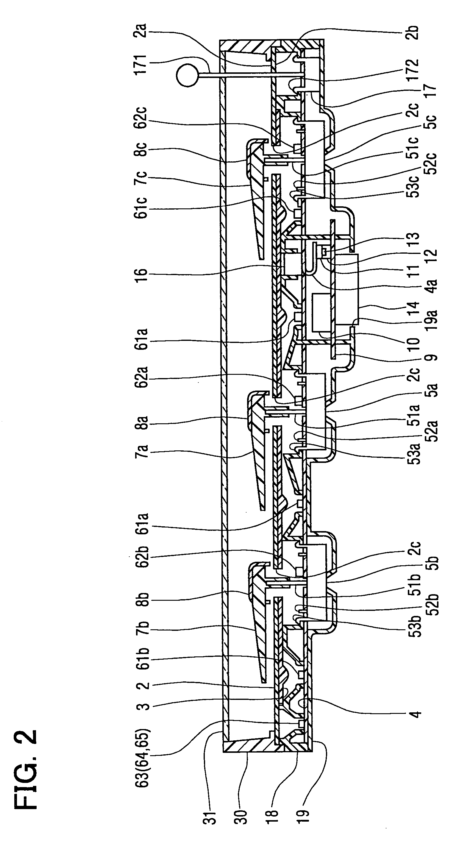
[0079] A combination meter 1 according to a second embodiment of the present invention will be explained with reference to FIG. 7. A dial plate 2 of the combination meter 1 of the second embodiment has a curved shape, and a flexible printed circuit board 4 is disposed parallel to the dial plate 2, as shown in FIG. 7. Movement 5a, 5b, 5c are disposed in such a manner that shafts 51a, 51b, 51c are perpendicular to the dial plate 2. LEDs 61a, 61b, 61c, 62a, 62b, 62c are disposed so that incident angles relative to the dial plate 2 are approximately zero degree.

[0080] The dial plate 2 and each of rotation display portions of rotation areas of the pointers 7a, 7b, 7c are parallel to each other. In other words, gaps between the dial plate 2 and each of the pointers 7a, 7b, 7c are maintained constant regardless of the respective rotation angles. This enhances an appearance of the combination meter 1. Further, the lights are emitted from the LEDs 61a, 61b, 61c, 62a, 62b, ...

Example

Third Embodiment

[0081] A meter 1 according to a third embodiment of the present invention will be explained with reference to FIG. 8. A dial plate 2 of the combination meter 1 of the third embodiment has a folded surface, and a flexible printed circuit board 4 is disposed parallel to the dial plate 2, namely the flexible printed circuit board 4 also has the fold surface as that of the dial plate 2. Similarly to the second embodiment, movement 5a, 5b are disposed in such a manner that shafts 51a, 51b are perpendicular to the dial plate 2. LEDs 61a, 61b, 62a, 62b are disposed so that incident angles relative to the dial plate 2 are approximately zero degree.

[0082] The dial plate 2 and each of rotation display portions of rotation areas of the pointer 7a, 7b are parallel to each other. In other words, gaps between the dial plate 2 and the pointers 7a, 7b are maintained constant regardless of the rotation angles. This enhances an appearance of the combination meter 1. Further, the lig...


PUM


Abstract

A circuit board is divided into two portions: a flexible printed circuit board; and a printed circuit board. On the flexible circuit board, movements whose layouts on the flexible circuit board are changed based on a design change in a dial plate due to a model change in a vehicle, light emitting diodes, a connector, a buzzer, and a changing-over switch are mounted. On the printed circuit board, a controller that radiates electrical noise during its operation is mounted. This enables a countermeasure for radiating of the electrical noise from the controller to be completed within the printed circuit board. This also enables a circuit design of the flexible printed circuit board to be easily performed. Man power for designing a combination meter can be thereby decreased; further, the combination meter capable of restricting generation of the electrical noise is achieved.

Description

CROSS REFERENCE TO RELATED APPLICATIONS [0001] This application is based on and incorporates herein by reference Japanese Patent Application No. 2003-274252 filed on Jul. 14, 2003. FIELD OF THE INVENTION [0002] The present invention relates to an indicating instrument that is mounted on a vehicle and rotates a pointer according to measured values. The present invention is suitably applied to an automobile. BACKGROUND OF THE INVENTION [0003] Conventionally, an indicating instrument for vehicles includes a dial plate having a plurality of display portions; light sources for luminously displaying the dial plate; movements for extending their pointer shafts forward of the dial plate; control circuits for driving the movements so that the pointer shafts are rotated by angles according to individual measured values detected by external detectors or the like and also for controlling ON and OFF of the light sources; and a printed circuit board. The printed circuit board is disposed backward...

Claims


Application Information

Patent Timeline
IPC IPC(8): B60K35/00G01D11/24B60K37/02G01D7/12
CPCB60K37/02G01D7/12B60K2350/302B60K2370/42
Inventor SUMIYA, MINORUNAKANE, HIDEYUKI
Owner DENSO CORP
Why Eureka
Try Eureka