Indicating instrument for vehicle
a technology for indicating instruments and vehicles, applied in the direction of identification means, instruments, audible signalling systems, etc., can solve the problems of radiated electrical noise and adversely affecting other electric devices mounted on the vehicle, and achieve the effect of securely reducing the electrical noise radiated from the control board and reducing the arising electrical nois
- Summary
- Abstract
- Description
- Claims
- Application Information
AI Technical Summary
Benefits of technology
Problems solved by technology
Method used
Image
Examples
first embodiment
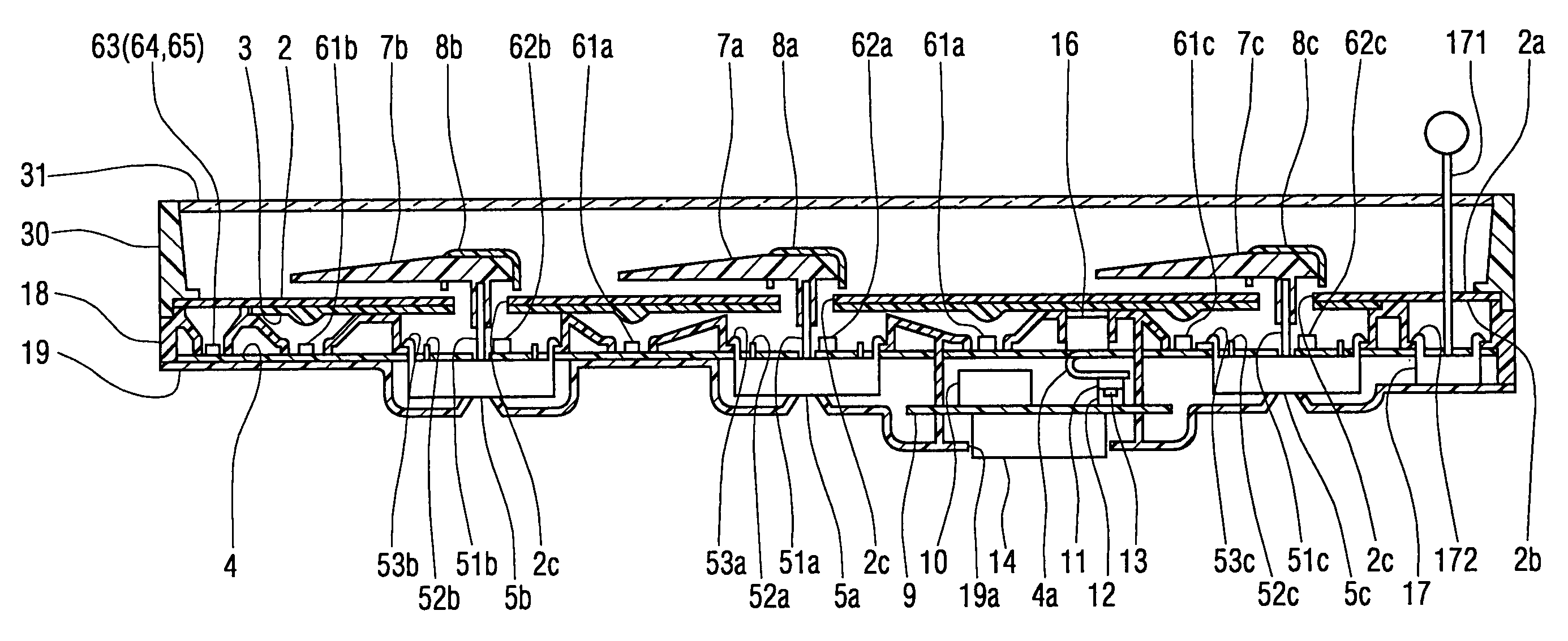
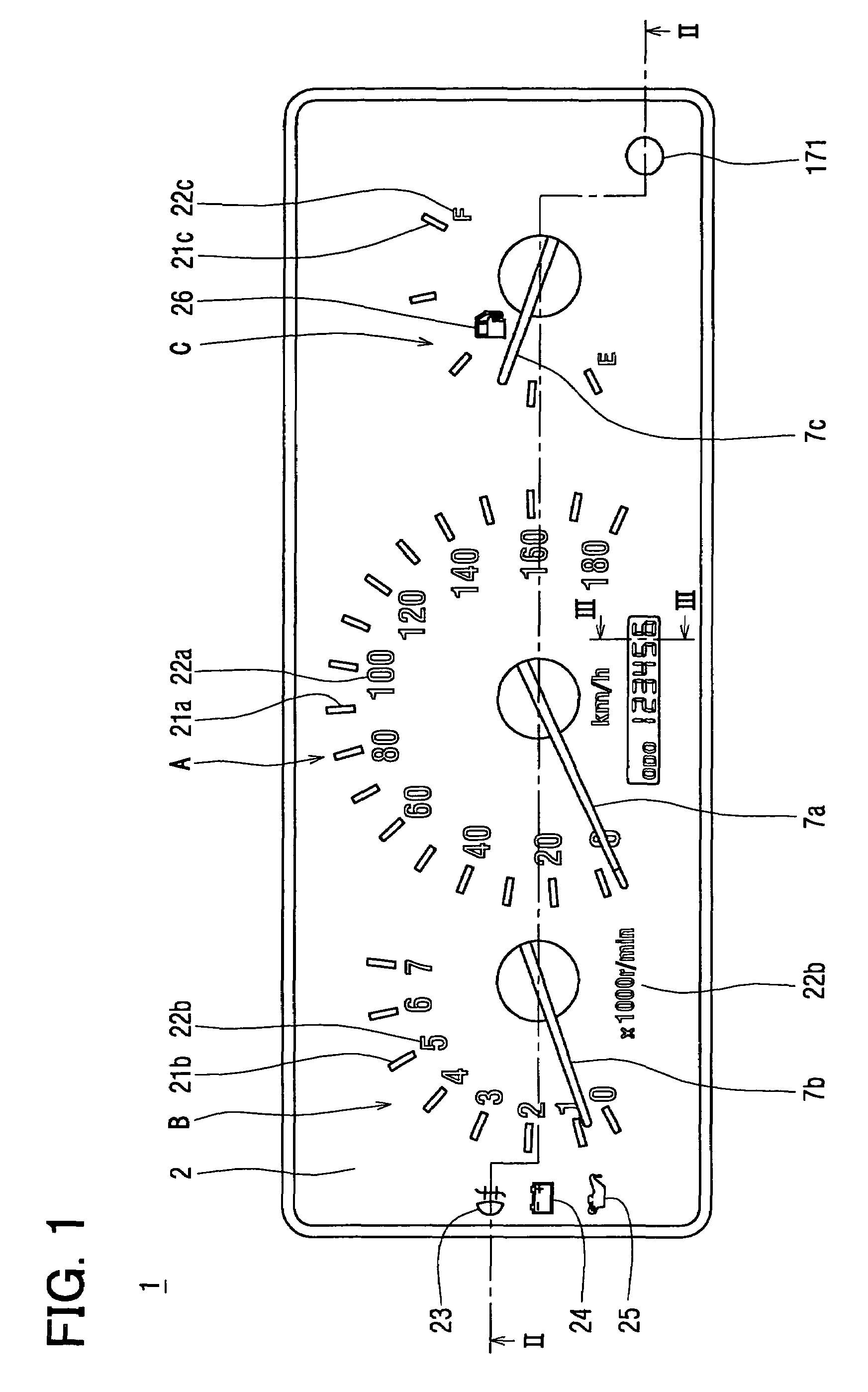
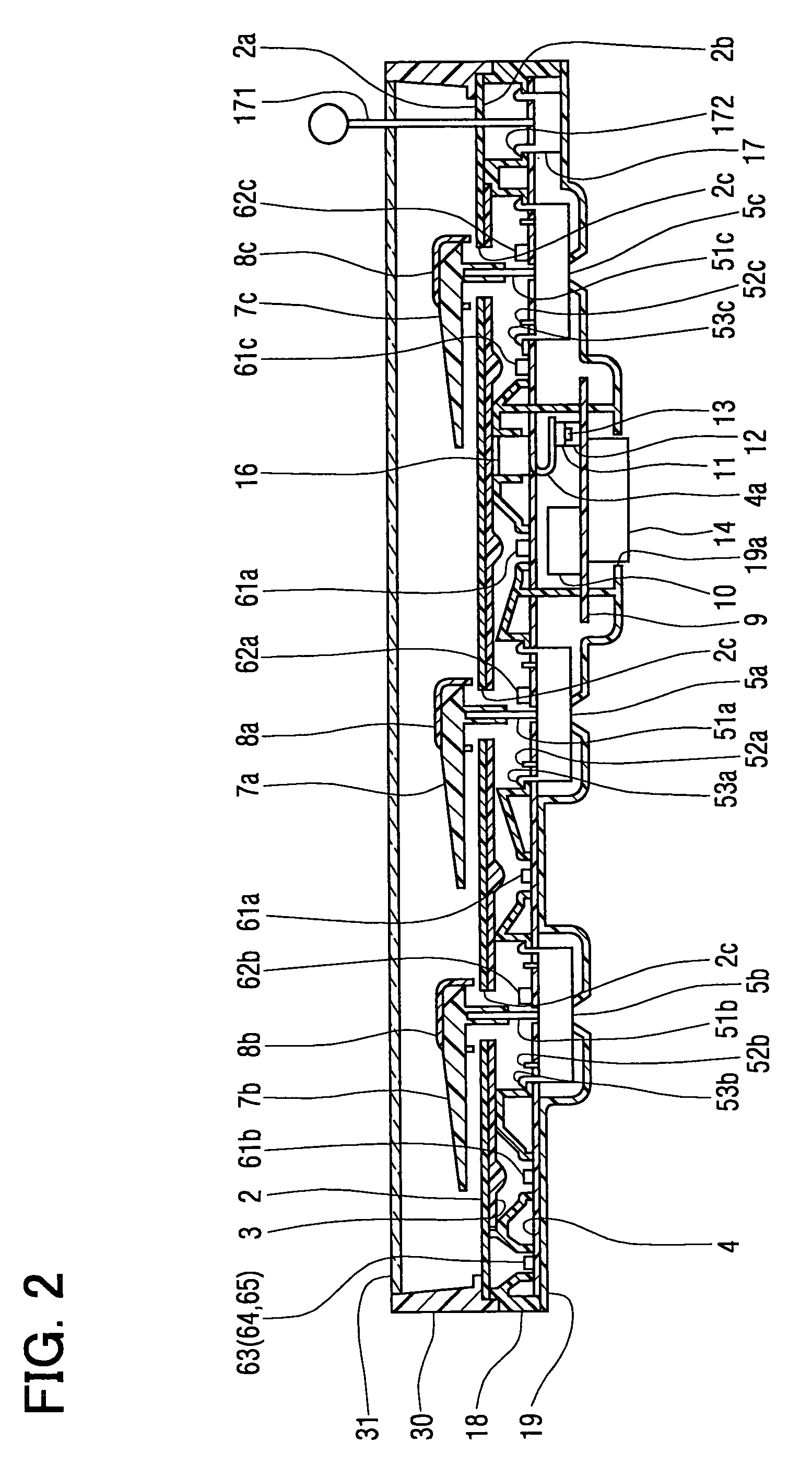
[0027]A combination meter 1 displays various information relating to a relevant vehicle and is disposed in such a manner that a driver seated in the front driver seat can see the combination meter 1.
[0028]The combination meter 1 primarily includes, in its dial plate 2, indicating instruments of a speedometer A, tachometer B, and fuel meter C; and display portions of a fog lamp indicator 23, voltage indicator 24, and oil pressure indicator 25, as shown in FIG. 1. Hereinafter, “front” or “forward” of the combination meter 1 is the side, surface, space, etc. of the combination meter 1 that faces the driver seat, while “back” or “backward” of the combination meter 1 is the side, surface, space, etc. of the combination meter 1 that is opposite to the “front” or “forward.”
[0029]The dial plate 2 is formed of a thin plate made of transparent polycarbonate resin etc. In the dial plate 2, scales, characters, and various indicators are formed, as shown in FIG. 1, i.e., the scales 21a and chara...
second embodiment
[0079]A combination meter 1 according to a second embodiment of the present invention will be explained with reference to FIG. 7. A dial plate 2 of the combination meter 1 of the second embodiment has a curved shape, and a flexible printed circuit board 4 is disposed parallel to the dial plate 2, as shown in FIG. 7. Movement 5a, 5b, 5c are disposed in such a manner that shafts 51a, 51b, 51c are perpendicular to the dial plate 2. LEDs 61a, 61b, 61c, 62a, 62b, 62c are disposed so that incident angles relative to the dial plate 2 are approximately zero degree.
[0080]The dial plate 2 and each of rotation display portions of rotation areas of the pointers 7a, 7b, 7c are parallel to each other. In other words, gaps between the dial plate 2 and each of the pointers 7a, 7b, 7c are maintained constant regardless of the respective rotation angles. This enhances an appearance of the combination meter 1. Further, the lights are emitted from the LEDs 61a, 61b, 61c, 62a, 62b, 62c perpendicularly t...
third embodiment
[0081]A meter 1 according to a third embodiment of the present invention will be explained with reference to FIG. 8. A dial plate 2 of the combination meter 1 of the third embodiment has a folded surface, and a flexible printed circuit board 4 is disposed parallel to the dial plate 2, namely the flexible printed circuit board 4 also has the fold surface as that of the dial plate 2. Similarly to the second embodiment, movement 5a, 5b are disposed in such a manner that shafts 51a, 51b are perpendicular to the dial plate 2. LEDs 61a, 61b, 62a, 62b are disposed so that incident angles relative to the dial plate 2 are approximately zero degree.
[0082]The dial plate 2 and each of rotation display portions of rotation areas of the pointer 7a, 7b are parallel to each other. In other words, gaps between the dial plate 2 and the pointers 7a, 7b are maintained constant regardless of the rotation angles. This enhances an appearance of the combination meter 1. Further, the lights are emitted from...
PUM
 Abstract
Description
Claims
Application Information
 - R&D
- Intellectual Property
- Life Sciences
- Materials
- Tech Scout
- Unparalleled Data Quality
- Higher Quality Content
- 60% Fewer Hallucinations
Browse by: Latest US Patents, China's latest patents, Technical Efficacy Thesaurus, Application Domain, Technology Topic, Popular Technical Reports.
© 2025 PatSnap. All rights reserved.Legal|Privacy policy|Modern Slavery Act Transparency Statement|Sitemap|About US| Contact US: help@patsnap.com


