Emergency lighting fixture in switch cover

a technology of emergency lighting and switch cover, which is applied in the direction of lighting and heating equipment, instruments, and power sources with built-in power, can solve the problems of inability to provide emergency lighting fixtures that can illuminate the indoor area, extra, and expensive bed lights, etc., and achieve the effect of improving the switch cover and looking calmly

Inactive Publication Date: 2005-01-20
YOON HEUNG SIK
View PDF7 Cites 41 Cited by
  • Summary
  • Abstract
  • Description
  • Claims
  • Application Information

AI Technical Summary

Benefits of technology

[0010] It is another object to provide an improved switch cover.
[0011] It is yet another object to provide an emergency lighting fixture in a switch cover for providing lighting to an indoor area during emergency situations involving power failures caused by an interruption of electrical service, fire, or natural disasters like earthquakes, whereby people do not become excessively anxious or feel insecure when hearing emergency alarms, but are enable to react to those emergency situations more bravely, and are able to calmly look for portable light sources like flashlights or candles.
[0012] It is still another object to provide an emergency lighting fixture in a switch cover as a replacement for a bed light or a supplementary light at night, while enabling the occupant to locate switch buttons for turning on the indoor lights.

Problems solved by technology

Therefore, when an interior area is dark, people have had difficulty in locating the button.
Because switch covers did not have a source of illumination that provided a soft-glow effect, people simply purchased extra, expensive bed lights or installed supplementary lights for nighttime use.
Furthermore, contemporary switch covers have not provided an emergency lighting fixture that is able to illuminate the indoor area during power failures caused by electrical short circuits, fire, earthquakes, etc.
When these emergency situations occur at night, resulting in unexpected power failures, most people feel insecure or anxious because they cannot see or recognize any of the objects or structural features around them.
Problems get worse because it is not easy to find portable light sources, such as flashlights or candles, at night without the aid of light.

Method used


Image

  • Emergency lighting fixture in switch cover
  • Emergency lighting fixture in switch cover
  • Emergency lighting fixture in switch cover

Examples


Embodiment Construction

[0022] Turning now to the drawings, the details of a first embodiment will be described by reference to the accompanying drawings. In the following description, well-known functions or constructions are not described in extensive detail since an exhaustive discussion would obscure the invention with unnecessary detail.

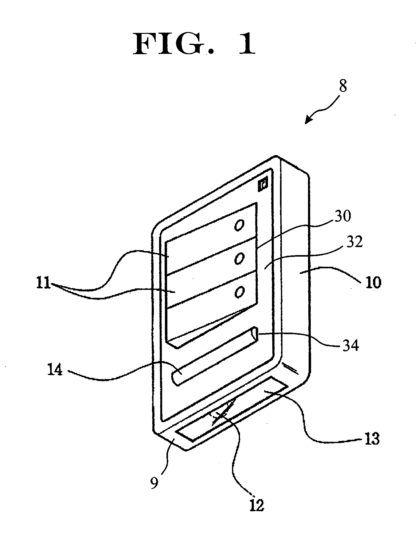
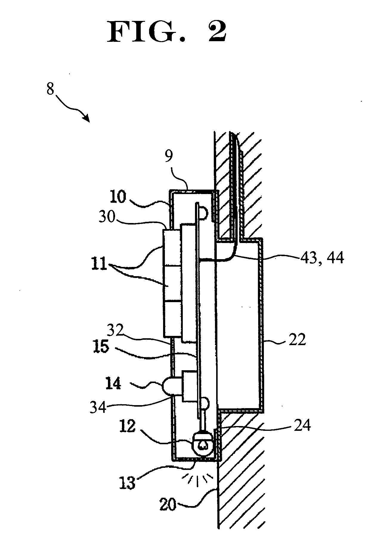
[0023]FIG. 1 is a perspective view of a switch cover 10 constructed according to a first embodiment of the present invention, and FIG. 2 and FIG. 3 respectively show a vertical cross-sectional view and a rear view of switch cover 10. FIG. 6 is a vertical cross-sectional view of switch cover 10 as constructed according to a second embodiment of the present invention, showing switch cover 10 mounted across flanges 24 and electrical box 22 that is recessed into the surface of a vertical wall 20 of an architectural structure, while FIG. 7 illustrates switch cover 10 fitted on its reverse side 25 with an electrical connector plug 26 bearing a plurality of electrical conduc...


PUM


Abstract

An emergency lighting fixture mounted under a switch cover that protects an electrical switch button for turning on/off the indoor lights, with a lamp concealed inside the cover providing lighting to an indoor area during normal times as well as in emergency situations involving power failures caused by shutoff of electricity, fire, or natural disasters like earthquakes. A transparent window on the same surface adjacent to lamp transmits light from the lamp. A switch on the front surface of the cover turns the lamp on or off, and a control circuit is mounted inside the cover, with a charging unit, a power-failure sensing unit, an emergency sensing unit, and a control unit.

Description

CLAIM OF PRIORITY [0001] This application makes reference to, incorporates the same herein, and claims all benefits accruing under 35 U.S.C. § 119 from an application entitled EMERGENCY LIGHTING FIXTURE IN SWITCH COVER earlier filed in the Korean Intellectual Property Office on 11 Jul. 2003 and thereby duly assigned Serial No. 2003-47326. BACKGROUND OF THE INVENTION [0002] 1. Field of the Invention [0003] The present invention relates to an emergency lighting fixtures generally, and, more particularly, to lighting fixtures mounted under switch covers that protect an indoor light switch button for turning indoor lights on and off, in which a lamp concealed inside the switch cover provides lighting to an indoor area during normal times as well as in emergency situations involving power failures caused by shutoff of electricity, fire, or natural disasters like earthquakes. [0004] 2. Description of the Related Art [0005] In general, a switch cover encompasses and protects a wall-mounted...

Claims


Application Information

Patent Timeline
Patent Type & Authority Applications(United States)
IPC IPC(8): F21V33/00F21S9/02F21Y101/00H01H9/02H01H9/18H05B37/02H05B41/14
CPCF21S9/02H01H9/182F21V33/0076H01H9/02
Inventor YOON, HEUNG-SIK
Owner YOON HEUNG SIK
Why Eureka
Try Eureka