Stereoscopic microscope

a stereoscopic microscope and microscope technology, applied in the field of stereoscopic microscopes, can solve the problems of poor image quality and field clipping, cumbersome adaptation of optical beam path of these supplementary systems to that of the stereo microscope, and considerable disadvantages of the microscope system or the image quality of the microscop

Inactive Publication Date: 2005-01-20
LEICA MICROSYSTEMS (SCHWEIZ) AG
View PDF9 Cites 9 Cited by
  • Summary
  • Abstract
  • Description
  • Claims
  • Application Information

AI Technical Summary

Benefits of technology

[0008] For a stereoscopic microscope, the present invention aims to invert laterally inverted, pseudo-stereoscopic image in a simple way, i.e. to image in a laterally correct and stereoscopically correct manner.

Problems solved by technology

However, the use of such SDI systems is accompanied by considerable disadvantages for the microscope system or the image quality of the microscope.
In particular, adapting the optical beam path of these supplementary systems to that of the stereo microscope has proved to be very cumbersome.
Frequently, this results in poor image quality and field clipping, which is caused by insufficient mechanical adaptation of the SDI-system to the microscope.
Further, the overall height of such SDI-systems influences the ergonomic overall height of the microscope in a negative way.

Method used


Image

  • Stereoscopic microscope
  • Stereoscopic microscope
  • Stereoscopic microscope

Examples


Embodiment Construction

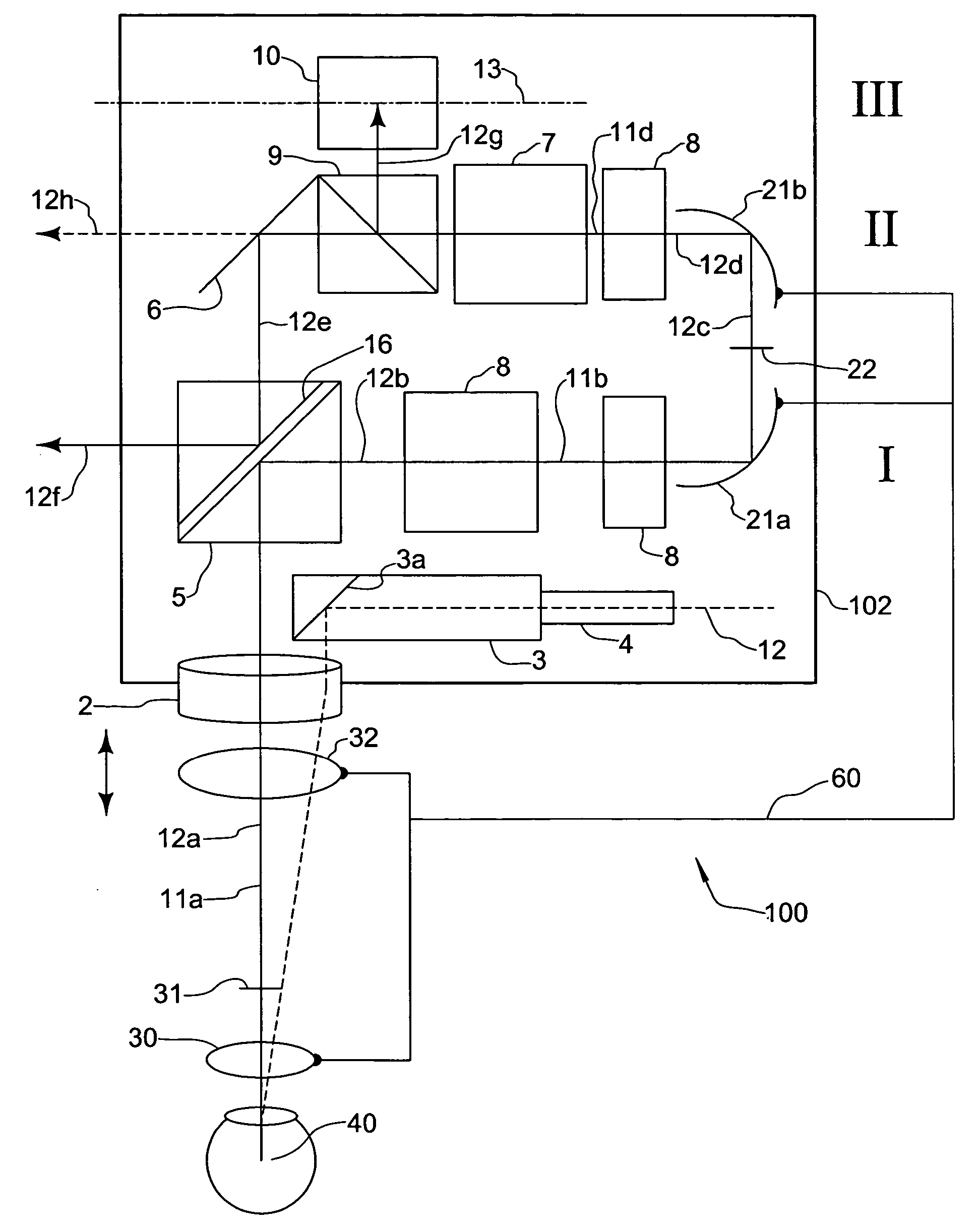
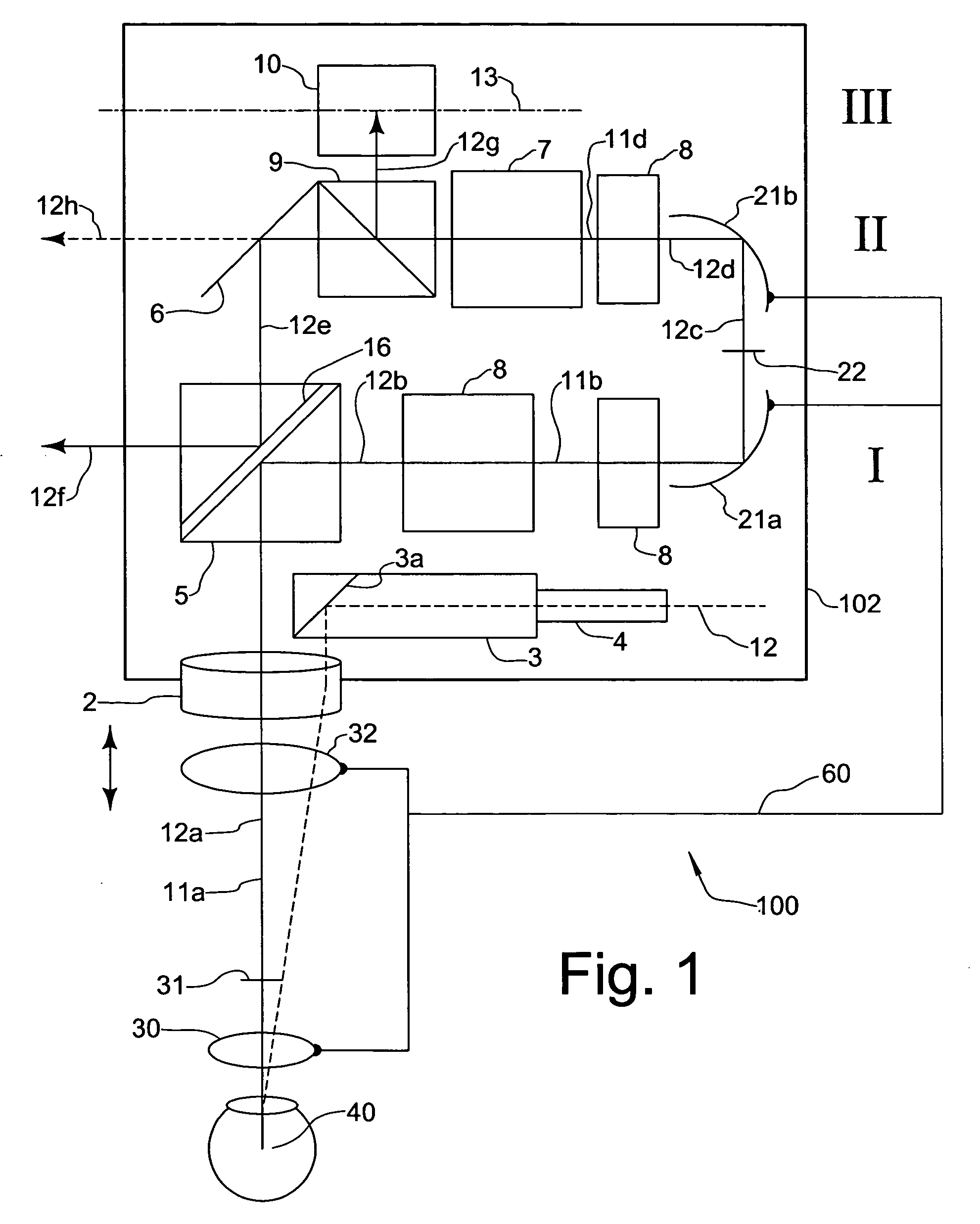
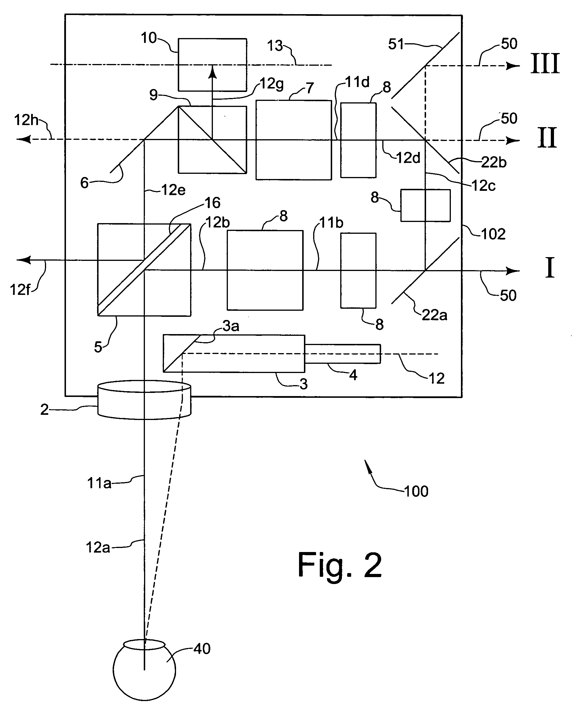
[0020] In FIG. 1, a preferred embodiment of the stereoscopic microscope according to the invention as a whole is designated by reference numeral 100. The stereoscopic microscope comprises a microscope body 102, in which a main objective 2 and a magnification system 7, which is especially designed as a zoom system, are provided as optical components.

[0021] The microscope further comprises deflector elements 5, 21a, 21b. By means of these deflector elements, viewing beams 12a to 12h, which emerge from an object 40 to be inspected, and which at first pass the main objective 2 substantially (at 21a) in vertical direction along the optical axis thereof, which is referred to as first optical axis 11a in the following, are deflectable into two substantially horizontally extending planes I and II of the microscope (at 12b, 12d). It can be seen that the magnifying system 7, in the embodiment shown is disposed in the second plane II of the microscope. The optical axes in the first and second...


PUM


Abstract

Stereoscopic microscope comprising an optical inverter system (21a, 21b) for erecting a pseudo-stereoscopic image and reversing the viewing beams thereof, wherein the inverter system comprises at least one deflector element (21a, 21b) having a focal power.

Description

CROSS-REFERENCE TO RELATED APPLICATIONS [0001] The present application claims priority of German patent application number 103 32 603.0 filed Jul. 17, 2003. FIELD OF THE INVENTION [0002] The present invention relates to a stereoscopic microscope of a type having an optical inverter system for erecting a pseudo-stereoscopic image and reversing of the viewing beams thereof. BACKGROUND OF THE INVENTION [0003] Ophthalmological microscopes as such are known. They comprise a main objective, a magnification system disposed thereafter, i.e. behind the main objective, and a binocular system with oculars (eyepieces). In order to provide a stereoscopic microscope in a magnification system, which is, for example, designed as a zoom system, the main beam path, which passes the main objective lens may be split into a number of beam paths. Further, ophthalmological microscopes are known, which allow for a simultaneous inspection of the object by a first user (main surgeon) and a second user (assis...

Claims


Application Information

Patent Timeline
Patent Type & Authority Applications(United States)
IPC IPC(8): G02B21/22
CPCG02B21/22
Inventor SANDER, ULRICH
Owner LEICA MICROSYSTEMS (SCHWEIZ) AG
Why Eureka
Try Eureka