Blood sampling device

a sampling device and blood technology, applied in the field of medical sampling devices, can solve the problems that the sampling device known has not been fully satisfactory to all users, and achieves the effect of increasing deformability and preserving sterility

Active Publication Date: 2005-01-20
FACET TECH LLC
View PDF60 Cites 245 Cited by
  • Summary
  • Abstract
  • Description
  • Claims
  • Application Information

AI Technical Summary

Benefits of technology

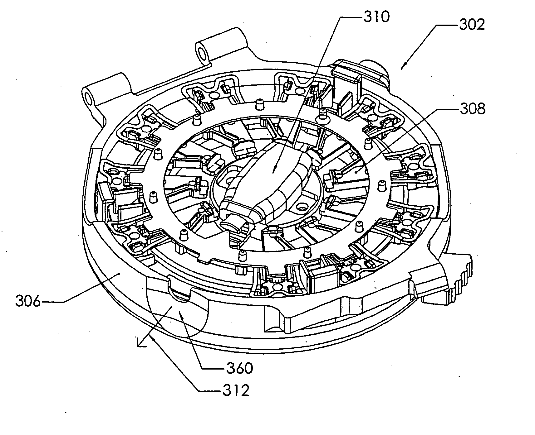
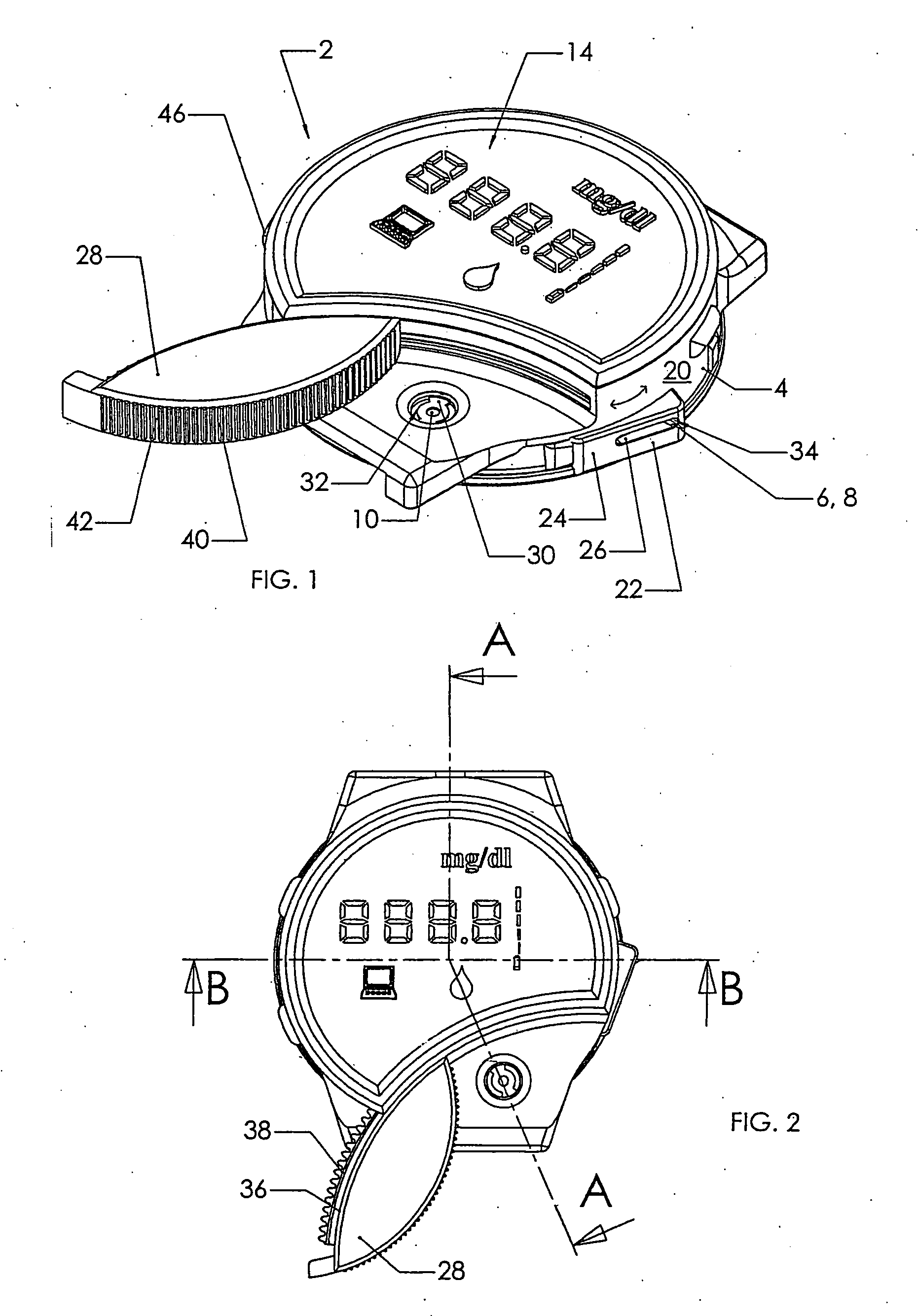
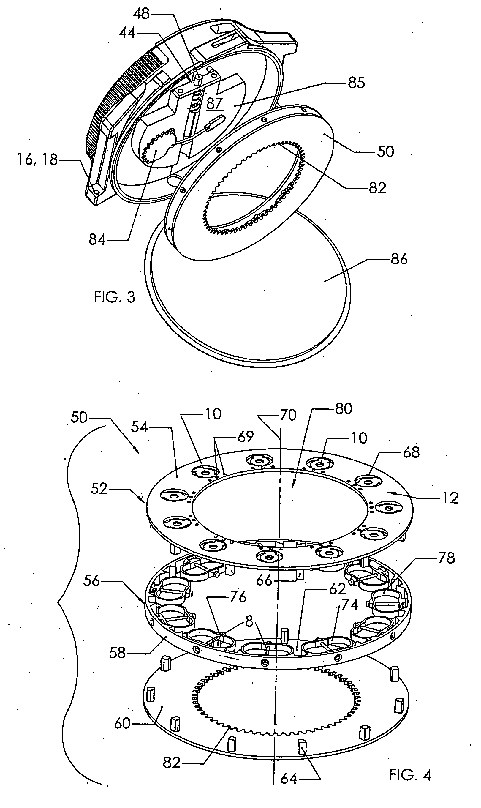
[0013] Various embodiments of the invention provide an “all-in-one” device which is compact, i.e., space-saving, and which is user-friendly and operator-friendly. Used test elements and / or lancets are preferably removed and replaced with unused test elements or lancets in a simple manner. The test element can, for example, be designed in the form of a membrane, which defines a measurement field that is wetted with the sample of blood taken, and which contains test reagents selected for the particular analysis to be performed. The analysis system can operate optically, for example, preferably by reflectometry, or electrochemically, or according to other means of analysis. In example embodiments, the test elements and / or the lancets are arranged into or onto a carrier or cassette, which can be inserted into the sampling device and which can be rotated or otherwise moved with respect to the housing, such that the test elements and / or lancets can be moved into working positions, located adjacent or apart from each other, as for example by rotating the carrier or cassette within the housing. Therefore, both the test elements and the lancets are preferably arranged on a rotatable carrier and can be moved into the working position, as by a rotary movement. A lancet is in its working position if it can be moved out through the puncture position to perform a puncture process. A test elements is in its working position if it can, in that position, be wetted with a sample of blood. The working positions of the lancets and the test elements can be adjacent or remote from one another. For example, the working position of the lancet can be at a 3-o'clock position on the housing and the working position of the test elements at a 6-o'clock position. Alternatively, the working positions for test elements and lancets are located at a single rotary position of the carrier by having the lancets arranged radially and the test elements arranged axially, for example by having the puncture position provided radially on the housing and the feed position provided axially on the housing.
[0045] According to an example embodiment of the invention, the lancets and / or the test elements are arranged concentrically about a point of rotation, so that they can be rotated into their individual operating positions. For that purpose, a first carrier for the lancets and a separate second carrier for the test elements are provided. To facilitate miniaturization of the device, the lancets, when arranged radially on the carrier, preferably leave a segment of a circle open so that the carrier can be inserted into the housing such that the plunger system extends into that circular segment. Because no lancet is placed in one circular segment (like a wedge of cake, which can cover for example 10° to 20° in the peripheral direction), the plunger system can penetrate in the radial direction into this region of the circular segment. Thus the plunger system does not hamper insertion of the carrier with the lancets into the housing. This further proves advantageous if, as described initially, a particular lancet and a plunger means of the plunger system are rotated relative to each other into a coupled connection.

Problems solved by technology

Known sampling devices have, however, not proven fully satisfactory to all users for a variety of reasons.

Method used


Image

  • Blood sampling device
  • Blood sampling device
  • Blood sampling device

Examples


Embodiment Construction

[0093] The present invention may be understood more readily by reference to the following detailed description of the invention taken in connection with the accompanying drawing figures, which form a part of this disclosure. It is to be understood that this invention is not limited to the specific devices, methods, conditions or parameters described and / or shown herein, and that the terminology used herein is for the purpose of describing particular embodiments by way of example only and is not intended to be limiting of the claimed invention. Also, as used in the specification including the appended claims, the singular forms “a,”“an,” and “the” include the plural, and-reference to a particular numerical value includes at least that particular value, unless the context clearly dictates otherwise. Ranges may be expressed herein as from “about” or “approximately” one particular value and / or to “about” or “approximately” another particular value. When such a range is expressed, anothe...


PUM


Abstract

A device (302) for sampling and / or analyzing blood or other body fluid of a subject. A housing (306) contains a plurality of lancets (308) and optionally includes test elements (324) to take up a sample of blood, an evaluation system and a display. A complete system that can be handled as a single device, for example in the form of a wristwatch, includes a multiplicity of test elements (324) and lancets (308), which can be brought successively to a working position to perform multiple measurements. A cassette or carrier (320) includes multiple lancets (308) and / or test elements (324), for insertion into the device.

Description

CROSS-REFERENCE TO RELATED APPLICATIONS [0001] This application claims the benefit of priority to German Patent Application, Serial No. DE 10208575.7, filed 21 Feb. 2002, German Patent Application, Serial No. DE 10245721.2, filed 24 Sep. 2002, and German Utility Model No. DE 20213607.8, filed 21 Feb. 2002, the content of which are hereby incorporated herein by reference in their entireties. FIELD OF THE INVENTION [0002] The present invention relates generally to a medical sampling device, and more particularly to a multiple use device for minimally-invasive sampling of blood and / or other body fluids for detection and analysis. BACKGROUND OF THE INVENTION [0003] Various devices are known for sampling blood and other body fluids for analysis of the condition of a human or other animal. For example, U.S. Pat. No. 5,971,941 is understood to show a cassette with test strips for placement by a slider. A lancet pierces the skin surface so that blood can be obtained for analysis. The lancet...

Claims


Application Information

Patent Timeline
Patent Type & Authority Applications(United States)
IPC IPC(8): A61B5/151A61B5/00A61B5/145A61B5/15A61B5/155A61B5/157
CPCA61B5/1411A61B5/14532A61B5/14546A61B2562/0295A61B5/15146A61B5/681A61B5/1486A61B5/150022A61B5/150183A61B5/150259A61B5/150358A61B5/150412A61B5/150519A61B5/150564A61B5/150572A61B5/150618A61B5/150725A61B5/15113A61B5/15117A61B5/1513A61B5/15151A61B5/15153A61B5/15161A61B5/15163A61B5/157A61B5/150969A61B5/150503A61B5/150702A61B5/15176
Inventor LEVAUGHN, RICHARD WKENNEDY, GWENN E.RUF, CHRISTOPHER J.SOLIS, MITCHELLROBBINS, AVI M.HEATH, JASON R.OSTERTAG, WOLFGANGLOHRENGEL, ARMINSTOHR, HERBERT
Owner FACET TECH LLC
Why Eureka
Try Eureka