Dust receptacle of robot cleaner and a method for removing dust collected therein

a robot cleaner and dust receptacle technology, which is applied in the direction of suction cleaners, cleaning filter means, cleaning equipment, etc., can solve the problems of troublesome in both cases, inconvenient and conventional methods of removing collected dust, and difficult to remove dus

Inactive Publication Date: 2005-01-27
SAMSUNG GWANGJU ELECTRONICS CO LTD
View PDF8 Cites 90 Cited by
  • Summary
  • Abstract
  • Description
  • Claims
  • Application Information

AI Technical Summary

Benefits of technology

[0009] An aspect of the present invention is to solve at least the above problems and / or disadvantages and to provide at least the advantages described below. Accordingly, an aspect of the present invention is to provide a dust receptacle of a robot cleaner which can be facilely emptied, and a method for removing dust collected therein.
[0011] The cover fit in the receptacle body comprises a filter to prevent the collected dust from flowing out through the air outlet. By existence of the filter, suction efficiency can be improved, and further, the dust does not flow into a suction motor disposed behind a discharge port.
[0013] A valve member is formed at an opening of the air inlet pipe unit to cover the opening by its own weight, the valve member being opened by pressure of an air flowed in through the air inlet. A user can conveniently mount or separate the dust receptacle using the handle unit. Further, by inwardly protruding the air inlet pipe unit and providing the valve member, the drawn-in air including dust is prevented from flowing back.
[0016] The sealing member has a flanged handle for easy separation from the dust outlet.

Problems solved by technology

However, such conventional way of removing the collected dust is inconvenient since all the processes are manually performed by the user.
Both cases are troublesome.
Therefore, the user needs to empty the dust receptacle of the robot cleaner frequently.
Therefore, it is hard to remove the dust, and the dust often remains in the dust collecting space even after emptying the dust receptacle.
Such remaining dust may gradually increase adhering inside and getting hard to be removed.
As a result, a suction efficiency is deteriorated.

Method used


Image

  • Dust receptacle of robot cleaner and a method for removing dust collected therein
  • Dust receptacle of robot cleaner and a method for removing dust collected therein
  • Dust receptacle of robot cleaner and a method for removing dust collected therein

Examples


Embodiment Construction

[0025] Hereinafter, an embodiment of the present invention will be described in detail with reference to the accompanying drawing figures.

[0026] In the following description, same drawing reference numerals are used for the same elements even in different drawings. The matters defined in the description such as a detailed construction and elements are nothing but the ones provided to assist in a comprehensive understanding of the invention. Thus, it is apparent that the present invention can be carried out without those defined matters. Also, well-known functions or constructions are not described in detail since they would obscure the invention in unnecessary detail.

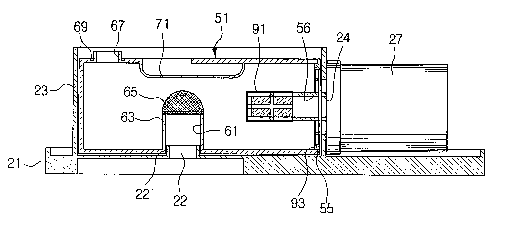
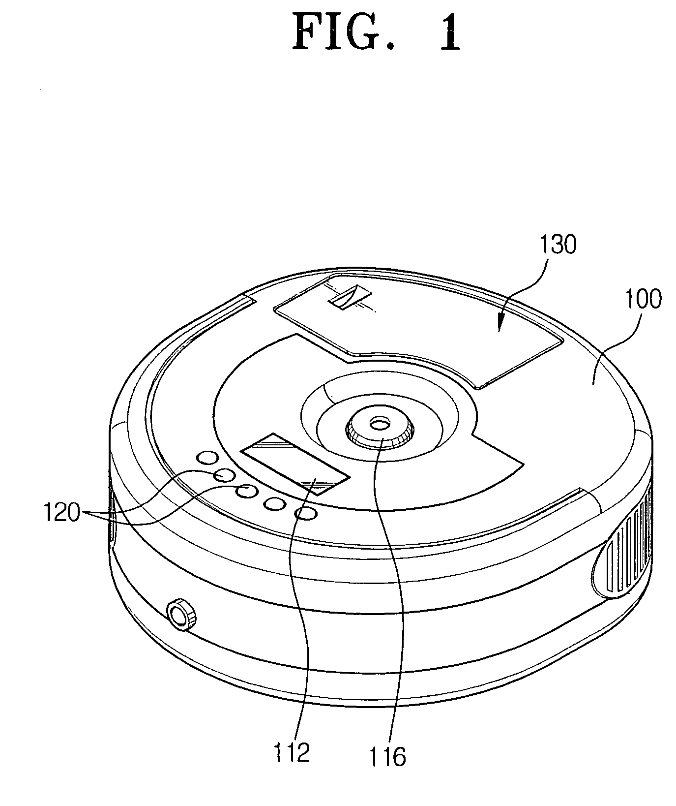
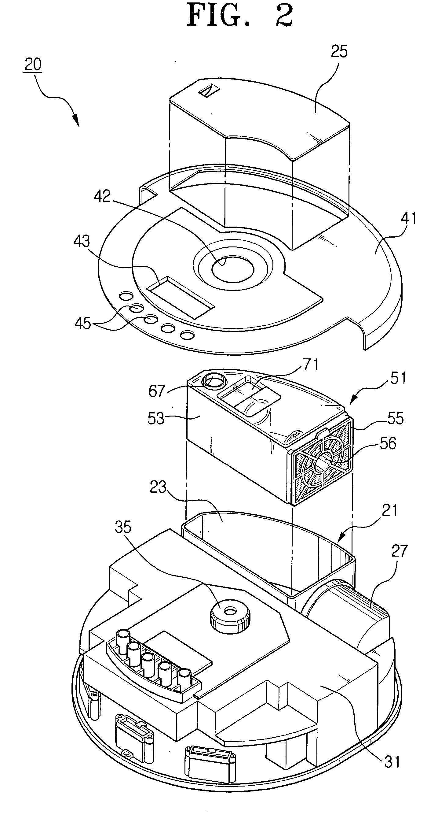
[0027]FIG. 1 is a perspective view of a robot cleaner applying a dust receptacle according to the present invention. The robot cleaner 20 has an upper casing 41. In a center of the upper casing 41, an image-capturing unit exposure hole 42 (FIG. 2) is formed, and at one side of the upper casing 41, a display window 43 ...


PUM


Abstract

A dust receptacle comprises a receptacle body having an air inlet and an air outlet, and detachably mounted in a dust collecting chamber of a robot cleaner, a cover fit in the receptacle body to open and close the air outlet, and a dust outlet formed in the receptacle body. Accordingly, the dust collected in the robot cleaner can be thoroughly and conveniently removed.

Description

CROSS-REFERENCE TO RELATED APPLICATIONS [0001] This application claims the benefit of Korean Application No. 2004-34150, filed May 14, 2004, in the Korean Intellectual Property Office, the disclosure of which is incorporated herein by reference. BACKGROUND OF THE INVENTION [0002] 1. Field of the Invention [0003] The present invention relates to a dust receptacle of a robot cleaner. More particularly, the present invention relates to a detachable dust receptacle mounted in a dust collecting chamber of a robot cleaner that automatically travels and cleans dust, and a method for removing dust collected therein. [0004] 2. Description of the Related Art [0005] In general, dust and an air are sucked into a robot cleaner together. Then, the dust is collected in a dust collecting chamber, and only the air is discharged to the outside. To remove the dust collected in the dust collecting chamber, a user has to open a door exposed outside of the robot cleaner, or take out a dust receptacle whi...

Claims


Application Information

Patent Timeline
Patent Type & Authority Applications(United States)
IPC IPC(8): A47L9/10A47L9/14A47L9/28A47L9/16
CPCA47L9/1409A47L2201/00A47L9/149
Inventor KIM, KI-MANSONG, JEONG-GON
Owner SAMSUNG GWANGJU ELECTRONICS CO LTD
Why Eureka
Try Eureka