
Steering control system

a control system and steering wheel technology, applied in fluid steering, electric steering, vehicle components, etc., can solve the problems of precise assist control of steering road wheels, the power steering device cannot sense the intention of the driver, and the steering operation is not assisted by, so as to reduce the control range of power steering the steered road wheels

Inactive Publication Date: 2005-01-27
HITACHI LTD +1
View PDF7 Cites 32 Cited by
  • Summary
  • Abstract
  • Description
  • Claims
  • Application Information

AI Technical Summary

Benefits of technology

In the above-mentioned steering control system of the steer-by-wire type steering device, the toque detected by the potentiometer is used as a parameter for controlling the steering assist operation. This means that even if the driver turns the steering wheel for the purpose of turning the vehicle, the potentiometer can not sense the driver's intention so long as the torsion bar is not twisted. Of course, in this case, the steering operation is not assisted by the electric actuator due to production of such dead operation zone.
If such dead operation zone is produced, a precise assist control for the steered road wheels, such as a control effected in accordance with the moving condition (for example, yaw rate) of the motor vehicle, is not correctly carried out. That is, in such case, a control range for power-steering the steered road wheels is reduced inevitably.
Accordingly, the present invention aims to provide a steering control system of steer-by-wire type steering device, which is free of the above-mentioned shortcoming.
In accordance with a first aspect of the present invention, there is provided a steering control system for controlling turning of steered road wheels of a motor vehicle in accordance with steering of a steering wheel. The steering control system comprises a steering angle sensor that detects a steering angle by which the steering wheel is turned; an actuator that turns the steered road wheels when operated; a vehicle operation condition sensor that detects an operation condition of the motor vehicle; a target value determining section that determines a steered angle target value of the steered road wheels in accordance with the steering angle detected by the steering angle sensor and the vehicle operation condition detected by the vehicle operation condition sensor; and an actuator drive circuit that drives the actuator in accordance with the steered angle target value.
In accordance with a second aspect of the present invention, there is provided a steering control system of a steer-by-wire type steering device, the steering device including an electric motor for turning steered road wheels of a motor vehicle, and a torsion bar operatively interposed between a steering wheel and the steered road wheels. The steering control system comprises a vehicle speed sensor that detects a running speed of the vehicle; a steering angle sensor that detects a steering angle by which a steering wheel of the vehicle is turned; a steered angle sensor that detects a steered angle of steered road wheels of the vehicle; a torque sensor that detects a torque applied to the torsion bar; a first means that, by processing the running speed of the vehicle detected by the vehicle speed sensor and the steering angle detected by the steering angle sensor, outputs a steered angle target value signal that represents a steered angle target value of steered road wheels of the vehicle; a second means that, by processing the steered angle target value signal from the first means and the steered angle detected by the steered angle sensor, outputs a corrected steered angle signal that represents a corrected value of the steered angle of the steered road wheels of the vehicle, the corrected steered angle signal being fed to the electric motor for controlling the turning of the steered road wheels; and a third means that, by processing the torque detected by the torque sensor, produces a steering reaction force that is to be applied to the steering wheel.

Problems solved by technology

This means that even if the driver turns the steering wheel for the purpose of turning the vehicle, the potentiometer can not sense the driver's intention so long as the torsion bar is not twisted.
Of course, in this case, the steering operation is not assisted by the electric actuator due to production of such dead operation zone.
If such dead operation zone is produced, a precise assist control for the steered road wheels, such as a control effected in accordance with the moving condition (for example, yaw rate) of the motor vehicle, is not correctly carried out.

Method used


Image

  • Steering control system
  • Steering control system
  • Steering control system

Examples


first embodiment

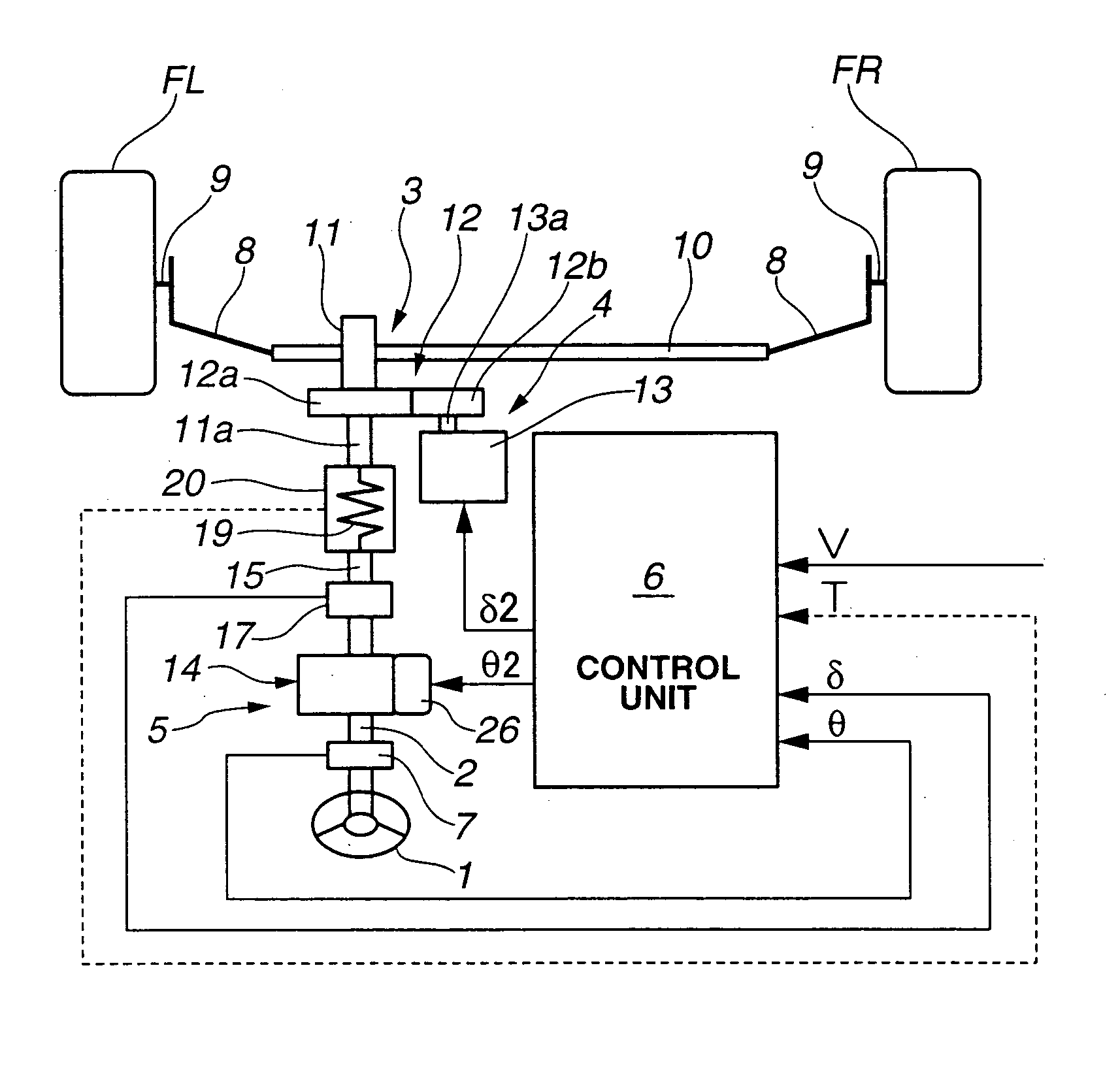
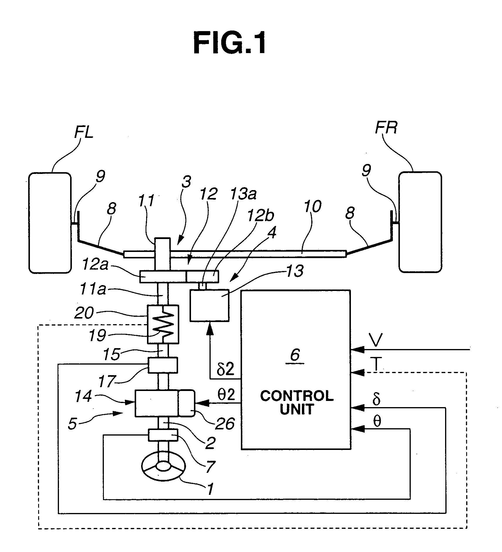
Referring to FIG. 1, there is schematically shown a steering control system of a steer-by-wire type steering device, which is the present invention.

The steering device shown is constructed to steer front right and front left steered road wheels FR and FL with the aid of an assisting force in accordance with turning of a steering wheel 1.

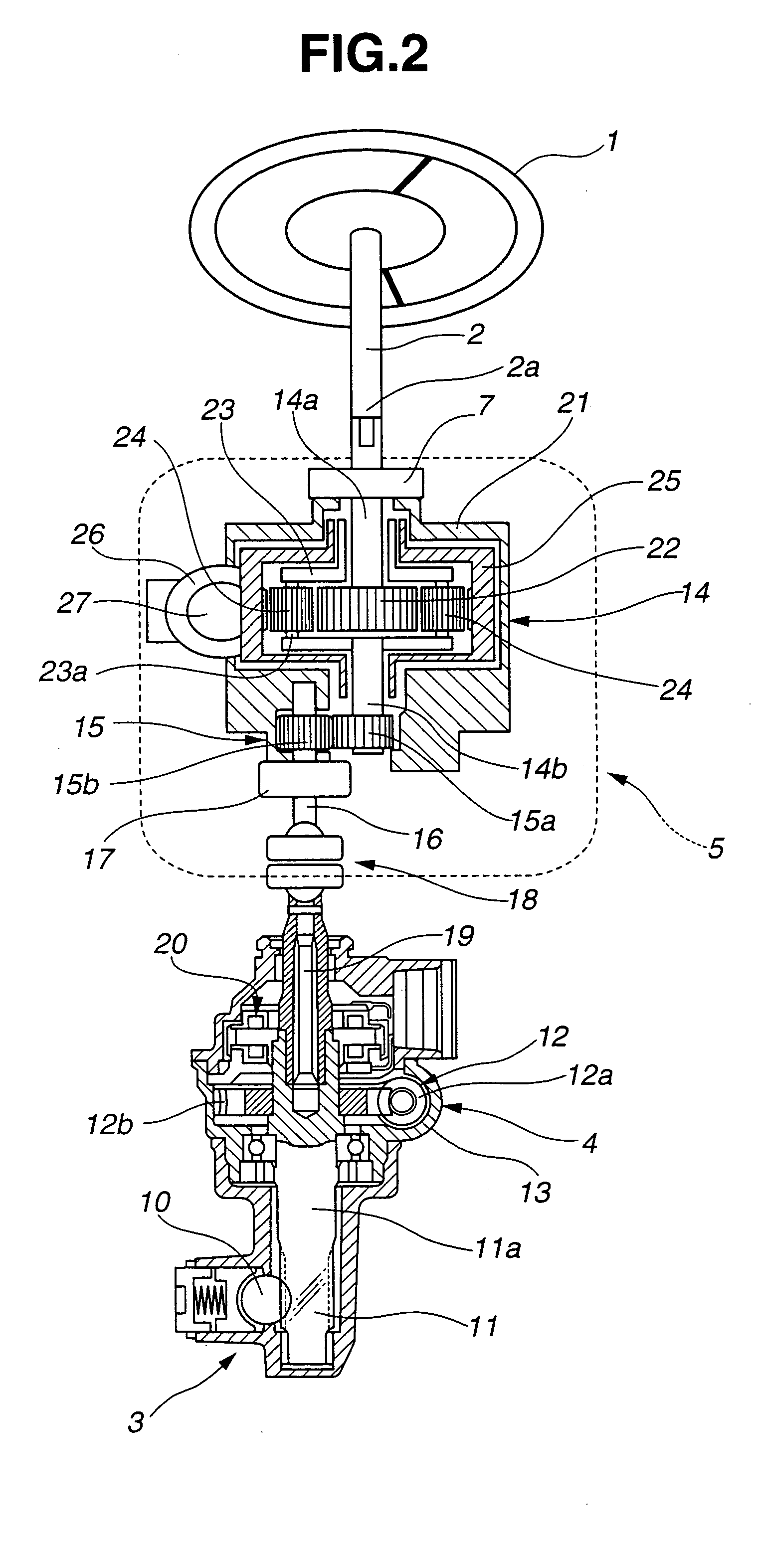
The steering device generally comprises a steering shaft 2 that is connected to and driven by steering wheel 1, a rack-and-pinion mechanism 3 that actuates front right and front left steered road wheels FR and FL, a power steering section 4 that drives rack-and-pinion mechanism 3 in accordance with a steering angle by which steering shaft 2 is turned, a back-up steering section 5 that is operatively independent from power steering section 4 and drives rack-and-pinion mechanism 3 in accordance with the steering angle of steering shaft 2, and an electric control unit 6 that controls mainly power steering section 4 in accordance with the steering ang...

second embodiment

Referring to FIG. 5, there is shown a block diagram of a control unit employed in the present invention.

As shown, in this second embodiment, for outputting steering angle target value “δ1” and steering reaction force target value “T1”, the target value determining circuit 40 of control unit 6 receives in addition to the above-mentioned vehicle speed signal “V” and steering angle signal “θ”, a yaw rate signalyaw” that is detected by a yaw-rate sensor 44. Due to addition of new factor “yaw”, much precise control for the steering is expected.

third embodiment

Referring to FIG. 6, there is shown but schematically a steer-by-wire type steering device to which a steering control system of the present invention is practically applied.

In this embodiment, the steered angle sensor 17 arranged between torsion bar 19 and rack-and-pinion mechanism 3 is constructed to serve also as a torque sensor that detects a torsional moment (viz., torque) of torsion bar 19. It is to be noted that the torsional moment (or torque) applied to torsion bar 19 can be derived indirectly from the operation of rack-and-pinion mechanism 3 and the operation of electric motor 13.


PUM


Abstract

A steering control system for controlling turning of steered road wheels of a motor vehicle in accordance with steering of a steering wheel, comprises a steering angle sensor that detects a steering angle by which the steering wheel is turned; an actuator that turns the steered road wheels when operated; a vehicle operation condition sensor that detects an operation condition of the motor vehicle; a target value determining section that determines a steered angle target value of the steered road wheels in accordance with the steering angle detected by the steering angle sensor and the vehicle operation condition detected by the vehicle operation condition sensor; and an actuator drive circuit that drives the actuator in accordance with the steered angle target value.

Description

BACKGROUND OF THE INVENTION 1. Field of the Invention The present invention relates in general to a control system of steering devices for wheeled motor vehicles, and more particularly to a steering control system of steer-by-wire type steering device wherein a steering wheel and steered road wheels are connected through an electronically controlled actuation system. 2. Description of the Related Art In order to clarify the task of the present invention, a known steering control system of steer-by-wire type steering device will be briefly described, which is shown in Japanese Laid open Patent Application (Tokkai) 2000-6829. In the steering control system of the publication, a torsion bar is interposed between a steering shaft on which a steering wheel is mounted and an input shaft to which a sun gear of a planetary gear unit is connected. Thus, when the steering wheel is turned, the torsion bar is twisted. The twisted degree (viz., torsional moment, or torque) of the torsion ba...

Claims


Application Information

Patent Timeline
Patent Type & Authority Applications(United States)
IPC IPC(8): B62D5/00B62D5/04B62D5/30B62D6/00B62D101/00B62D113/00B62D119/00
CPCB62D6/008B62D5/008
Inventor FUKUSHIMA, NAOTONAKAMURA, TOSHIAKISHIINO, KOHTAROTANIUCHI, SATOSHIYAMANO, KAZUYAMASAKI, MINORU
Owner HITACHI LTD
Learn More