

Ink-jet head driving method and ink-jet recording apparatus
a driving method and inkjet technology, applied in the direction of printing, other printing apparatus, etc., can solve the problems of inability to achieve desired printing results, drop is ejected unstably, and the amount of ink consumed increases, so as to prevent ink from increasing viscosity and coagulation
- Summary
- Abstract
- Description
- Claims
- Application Information
AI Technical Summary
Benefits of technology
Problems solved by technology
Method used
Image

Examples
first embodiment
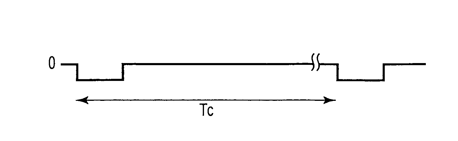
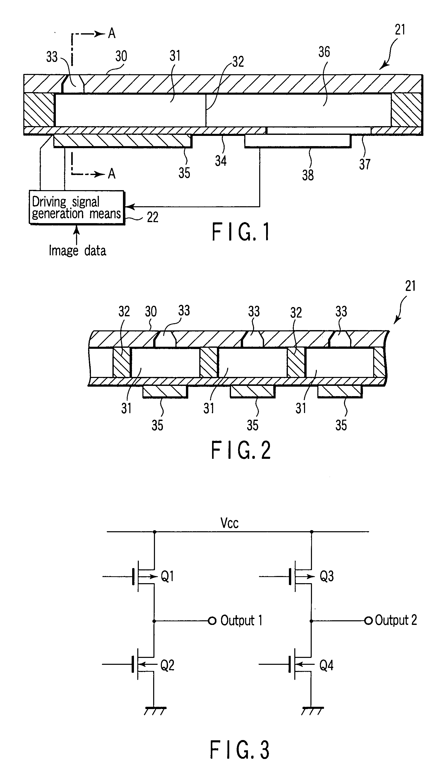
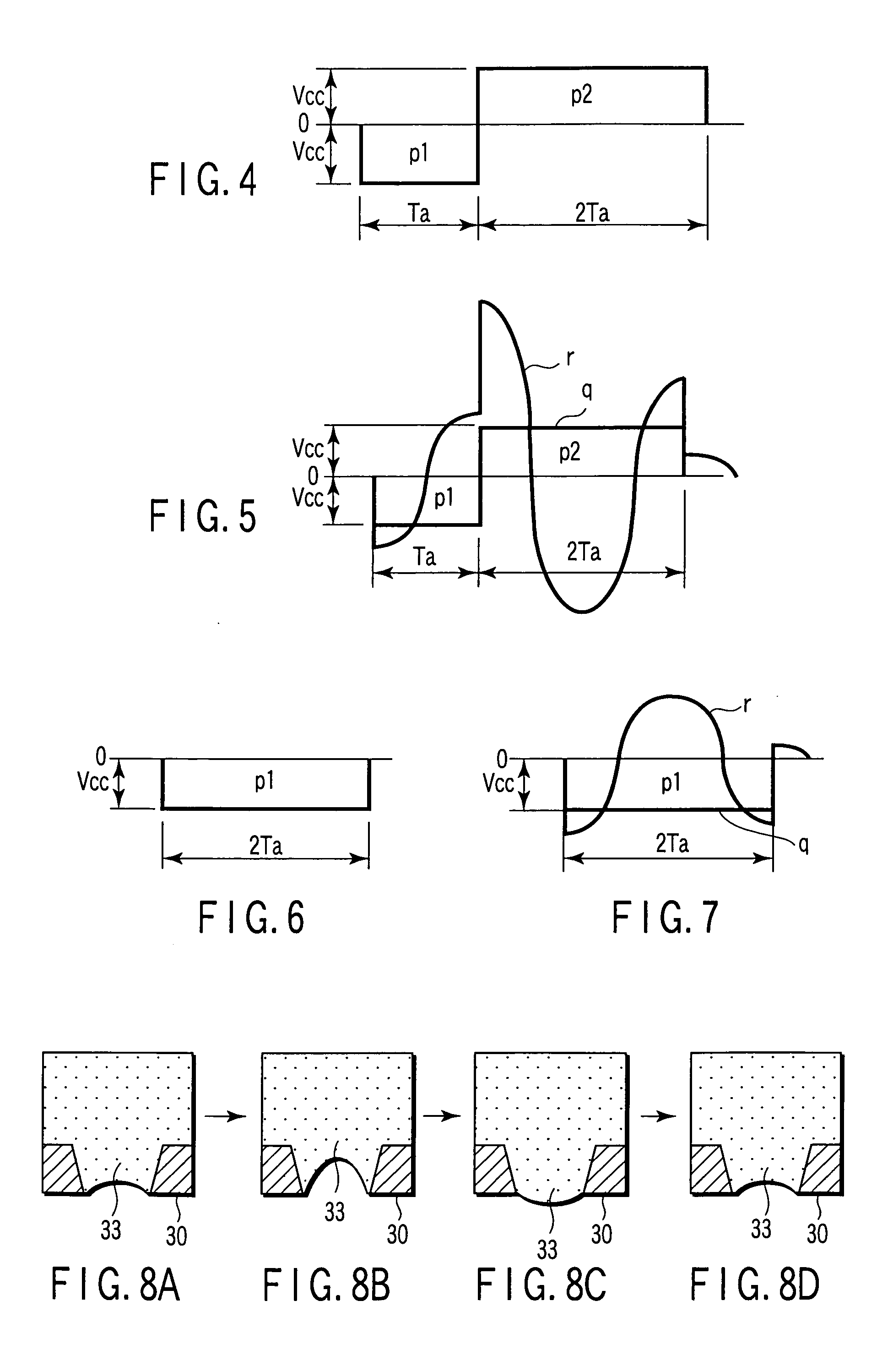
[0039] Embodiments of the present invention will now be described with reference to the accompanying drawings. FIG. 1 is a sectional view of the main part of an ink-jet recording head according to the present invention. FIG. 2 is a sectional view taken along line A-A of FIG. 1. Referring to FIGS. 1 and 2, an ink jet head 21 is divided into a plurality of pressure chambers 31 for containing ink. A partition wall 32 is formed between adjacent pressure chambers 31. Each of the pressure chambers 31 has a nozzle 33 for ejecting ink drops. The nozzle 33 is formed in a nozzle plate 30. A vibrating plate 34 is formed on the bottom of each of the pressure chambers 31. A piezoelectric member 35 is fixed on the underside of the vibrating plate 34. The vibrating plate 34 and piezoelectric member 35 make up an actuator.
[0040] The ink-jet head 21 includes a common pressure chamber 36 communicating with each of the pressure chambers 31. The common pressure chamber 36 is supplied with ink from ink ...
second embodiment
[0062] In order to resolve the above problem, an ink-jet recording apparatus according to the present invention will now be described with reference to FIG. 10. Referring to FIG. 10, a tube 42 is connected to a common ink chamber 36 through an ink supply inlet 37 and a filter 41. The tube 42 is provided with an ink filling pump 43 that allows ink to flow in forward and backward directions. The inlet of the pump 43 is connected to an ink bottle 44. A driving unit 45 controls the pump 43 to allow ink to flow forward and backward.
[0063] Assume that the ink-jet recording apparatus with the above configuration turns off and sits idle for a long period of time and ink in the nozzle 33 considerably increases in viscosity or solidifies. First, the pump 43 is driven in the backward direction to cause ink to flow from the nozzle 33 in the direction of arrow a through the tube 42. The ink is agitated in a pressure chamber 31. Then, the pump 43 is driven in the forward direction to discharge in...
PUM
 Abstract
Description
Claims
Application Information