
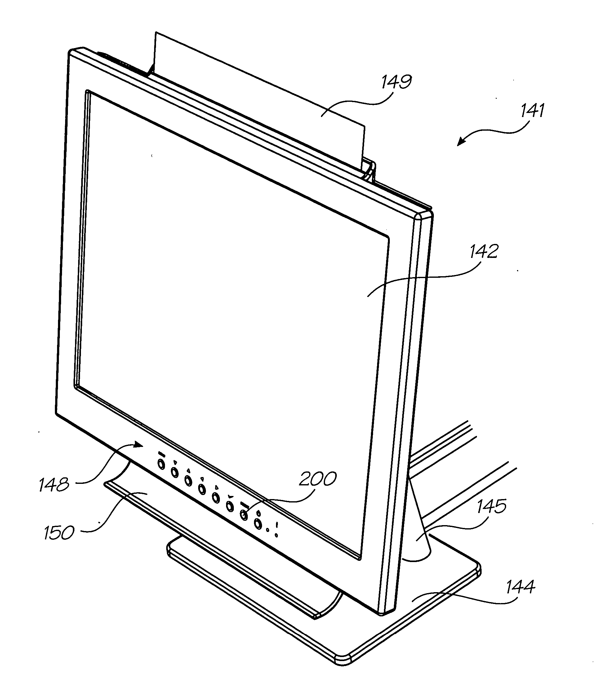
Display device configured such that an edge of print media is visible above an upper edge of the device

a display device and print media technology, applied in printing, electrical apparatus construction details, printing mechanisms, etc., can solve the problems of occupying additional space in the user's work area, tft lcd display, and bulky printers,

Inactive Publication Date: 2005-01-27
ZAMTEC
View PDF17 Cites 9 Cited by
  • Summary
  • Abstract
  • Description
  • Claims
  • Application Information

AI Technical Summary

Benefits of technology

[0041] Optionally the stand enables continuous adjustment between the operative positions.
[0056] Optionally the device further includes at least two of the printheads, the printheads being disposed on either side of a path through which the paper is fed for printing, thereby enabling substantially simultaneous printing of both sides of a sheet of paper.
[0070] Optionally the printer includes at least two of the printheads, the printheads being disposed on either side of a path through which print media is fed for printing, thereby enabling substantially simultaneous printing of both sides of the print media.
[0089] Optionally the device further includes at least two of the printheads, the printheads being disposed on either side of a path through which the paper is fed for printing, thereby enabling substantially simultaneous printing of both sides of a sheet of paper.
[0170] Optionally the device further includes at least two of the printheads, the printheads being disposed on either side of a path through which the paper is fed for printing, thereby enabling substantially simultaneous printing of both sides of a sheet of paper.
[0194] Optionally the device further includes at least two of the printheads, the printheads being disposed on either side of a path through which the paper is fed for printing, thereby enabling substantially simultaneous printing of both sides of a sheet of paper.

Problems solved by technology

Typically, flat panel displays, including TFT LCD displays, are more expensive than Cathode Ray Tube (CRT) display of comparable performance.
Printers can be bulky, and tend take up additional space in a user's work area.
Where space is at a premium, such printers can be intrusive or at least inconvenient.
In many cases where a flat panel display is selected, space is already at a premium, so printers can exacerbate the problem.

Method used


Image

  • Display device configured such that an edge of print media is visible above an upper edge of the device
  • Display device configured such that an edge of print media is visible above an upper edge of the device
  • Display device configured such that an edge of print media is visible above an upper edge of the device

Examples


Embodiment Construction

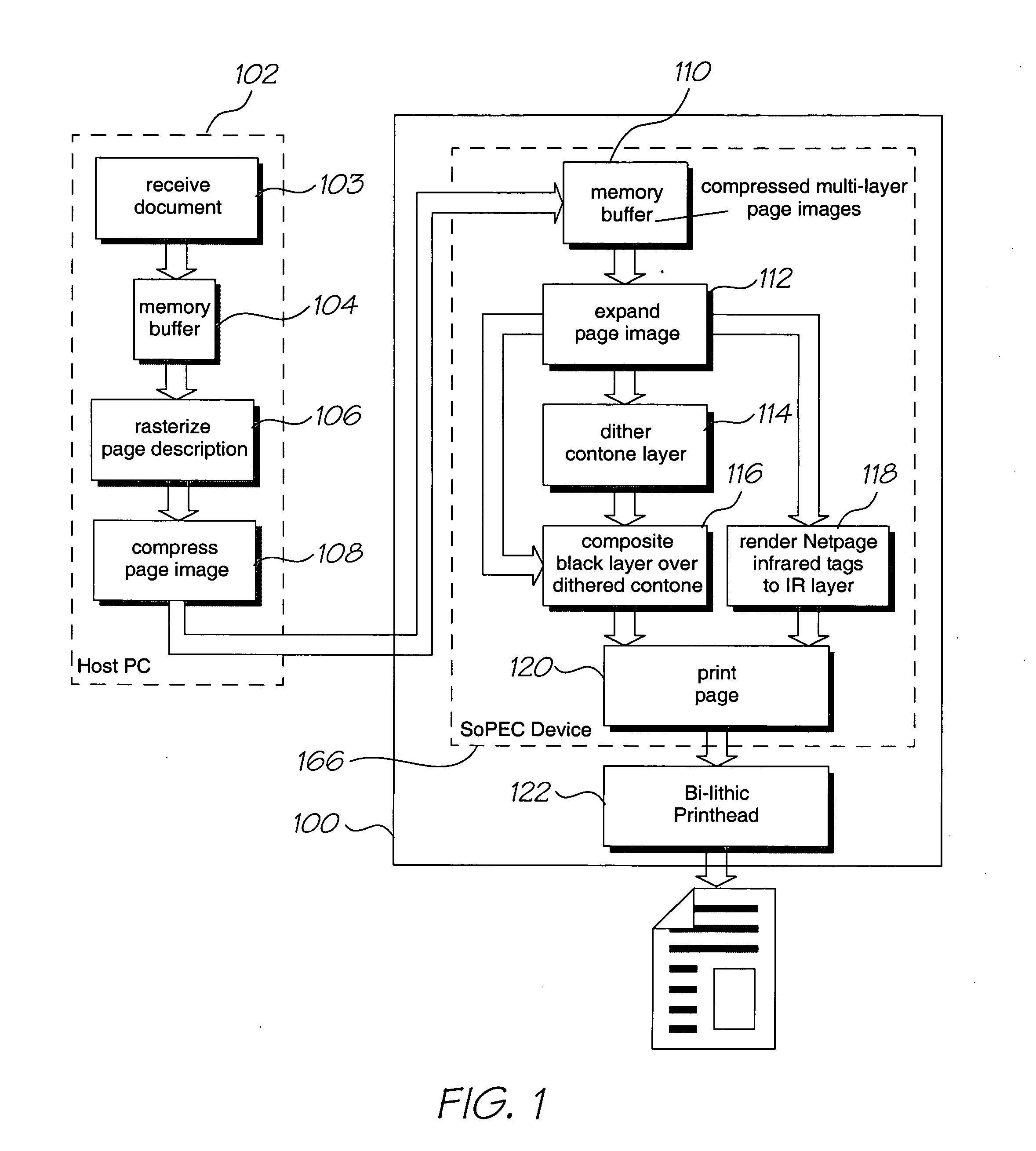
[0259] As shown in FIG. 1, in the preferred embodiment, the printing aspect of the invention is embodied in an A4 / Letter printer 100 that prints documents supplied by a computer system 102. The computer system 102 is programmed to perform various steps involved in printing a document, including receiving the document (step 103), buffering it (step 104) and rasterizing it (step 106), and then compressing it (step 108) for transmission to the printer 100.

[0260] The compressed, multi-layer page image is buffered (step 110) upon receipt in the printer 100, then expanded (step 112). The expanded contone layer is dithered (step 114) and then the black layer from the expansion step is composited over the dithered contone layer (step 116). Coded data can also be rendered (step 118) to form an additional layer, to be printed (in the preferred form) using an infrared ink that is substantially invisible to the human eye. The black, dithered contone and infrared layers are combined (step 120) ...


PUM


Abstract

A display device for use as a computer monitor, the display device comprising: a flat panel display; a printer, including a printhead for printing onto paper; and a sheet feeder for feeding print media to the printhead, the device being configured such that standard print media to be printed is supported, immediately prior to commencement of printing, such that at least an edge of the print media is visible above an upper edge of a the flat panel display.

Description

[0001] This is a Continuation-In-Part of Ser. No. 10 / 803,074 filed on Mar. 18, 2004 CO-PENDING APPLICATIONS [0002] Various methods, systems and apparatus relating to the present invention are disclosed in the following co-pending applications filed by the applicant or assignee of the present invention simultaneously with the present application: [0003] FDP008US FDP009US FPD010US FDP011US FDP013US FDP014US FDP015US [0004] The disclosures of these co-pending applications are incorporated herein by cross-reference. Each application is temporarily identified by its docket number. This will be replaced by the corresponding application number when available. CROSS-REFERENCES [0005] Various methods, systems and apparatus relating to the present invention are disclosed in the following co-pending applications filed by the applicant or assignee of the present invention. The disclosures of all of these co-pending applications are incorporated herein by cross-reference. 10 / 727,18110 / 727,16210...

Claims


Application Information

Patent Timeline
IPC IPC(8): B41J3/00G06F1/16G06F15/00H05K7/00
CPCB41J2/01B41J2/14427B41J2/175G06F1/1601B41J3/445B41J3/46B41J2002/14435B41J3/28H05K7/00
Inventor SILVERBROOK, KIA
Owner ZAMTEC
Learn More