
Layout editing program

a technology of layout and program, applied in the field of printing system, can solve the problems of inconvenient printing layout operation, user's inability to produce printed output having color that is consistent with what the user, and the inability of conventional systems to automatically adjust color

Inactive Publication Date: 2003-09-04
SEIKO EPSON CORP
View PDF32 Cites 77 Cited by
  • Summary
  • Abstract
  • Description
  • Claims
  • Application Information

AI Technical Summary

Benefits of technology

button 115, and EXPORT button 116. The order of arrayal of these buttons 111 through 116 from left to right parallels retouching operational procedure as typically carried out by a user. Such operational procedure is more or less as follows.[0106] To wit, firstly, if BROWSE button 111 is pressed, BROWSE mode is entered, wherein thumbnail images of all of the photo image files within desired photo folder(s) 12 may be browsed and desired photo image file(s) may be selected therefrom. Next, if TRIM button 112 is pressed, TRIM mode is entered, wherein photo image(s) selected while in BROWSE mode may be displayed in its or their entirety and unwanted region or regions other than region or regions of such image(s) which is or are desired to be printed may be cropped away so as to extract only the region or regions of such image(s) which is or are desired to be printed. Next, if RETOUCH button 113 is pressed, RETOUCH mode is entered, wherein desired brush(es) may be used to apply desired modifications at desired location(s) within such photo image(s). Next, if COLOR / TONE button 114 is pressed, COLOR / TONE mode is entered, wherein color adjustment filter(s) may be used to apply desired color adjustment(s) to entire photo image(s). Next, if

Problems solved by technology

One factor which interferes with this ability is the fact that the characteristics affecting color in digital cameras, computer display monitors, printers, and other such image processing devices differ from device to device.
Despite this, conventional systems do not possess the capability to automatically adjust color to compensate for differences in color characteristics among devices.
Unless the user has a good understanding of the color characteristics of each device and manually adjusts color himself or herself in, for example, photo retouching software or the like, the user will be unable to produce printed output having color that is consistent with what the user was expecting.
However, such print layout operations also represent an inconvenience in conventional systems.

Method used


Image

  • Layout editing program
  • Layout editing program
  • Layout editing program

Examples


Embodiment Construction

[0051] Before beginning description of embodiments, "color profiles" and "color matching," repeated reference to which is made throughout such description, will be described.

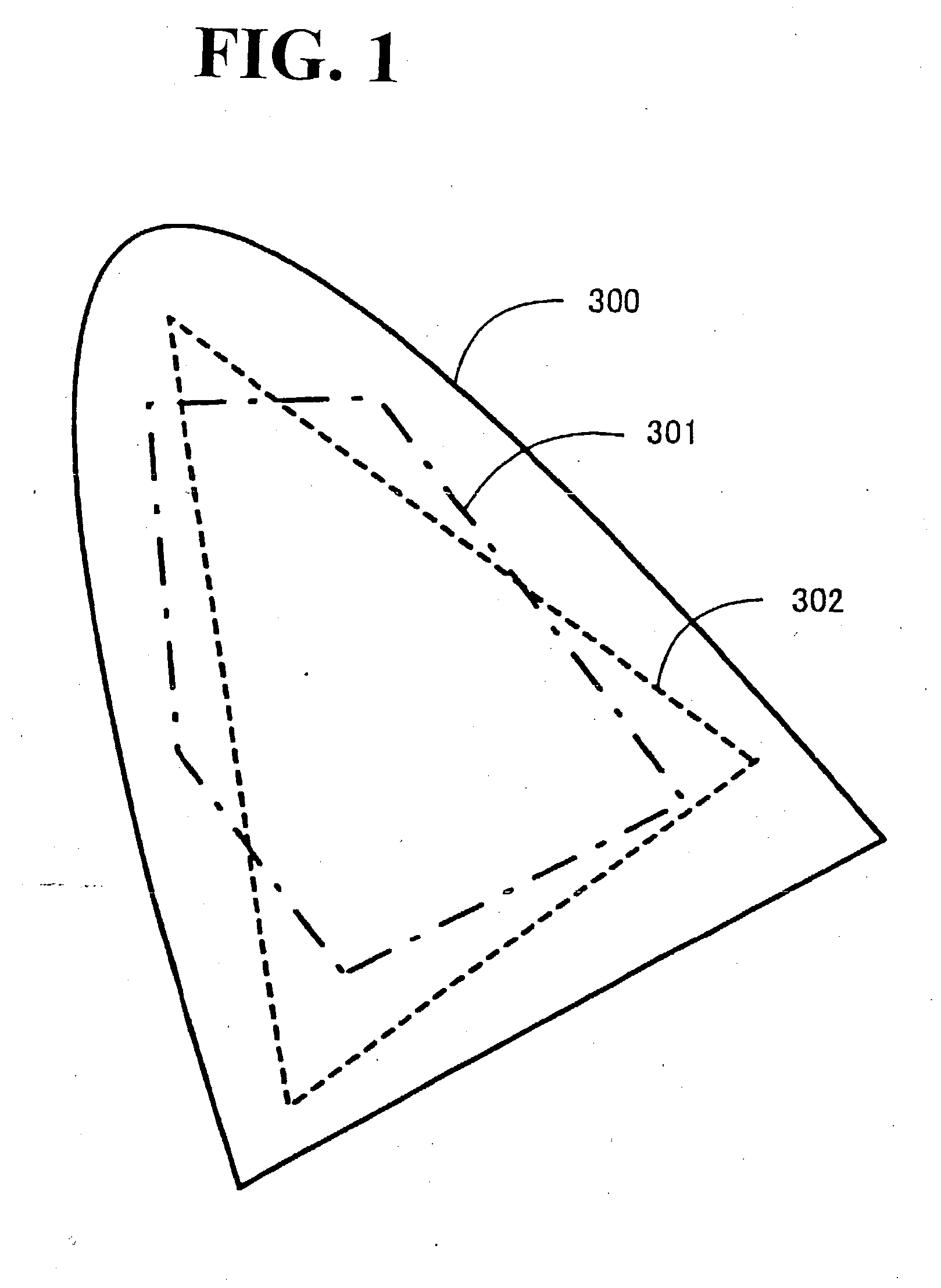
[0052] Each of the various image processing devices (e.g., cameras, image scanners, display monitors, printers, etc.) has its own unique color space(s) in which operations are carried out and its own unique gamut(s), i.e., locus or loci of colors that can be created. For example, while display monitors all operate within RGB color space, gamut will vary from monitor to monitor. Likewise, gamuts of printers, which carry out operations in CMYK color space, will be different for different printers. Furthermore, even the same printer will exhibit different gamuts depending upon the type of ink and printing medium (printing paper) used therewith.

[0053] FIG. 1 is drawing showing a schematic example of gamuts of different devices. At FIG. 1, reference numeral 300 indicates gamut visibly perceivable by human beings, ref...


PUM


Abstract

Operations wherein print layout(s) is or are edited and print job(s) is or are created are made capable of being carried out efficiently. In template mode, apportionment of image(s) is ordinarily carried out with template(s) being set for each individual page. Group(s) are closed for each page. Package(s) may be such that a plurality of templates are treated as a single pack (multiple pages), and group(s) within package(s) may be such that all are treated as if it or they are the same group(s), the same image(s) being assignable thereto. List(s) (dropdown list(s)) of name(s) of template(s) corresponding to print media size(s) specified at media / printer selection area 146 may be displayed at screen(s) which is or are presented when package(s) is or are employed. Layout editor(s) obtain such template information (dropdown list(s)) from print server machine(s). Upon selection of only a single desired template name from such a list, description(s) of that template name may be displayed below that list and selected template(s) may be displayed at layout display area(s).

Description

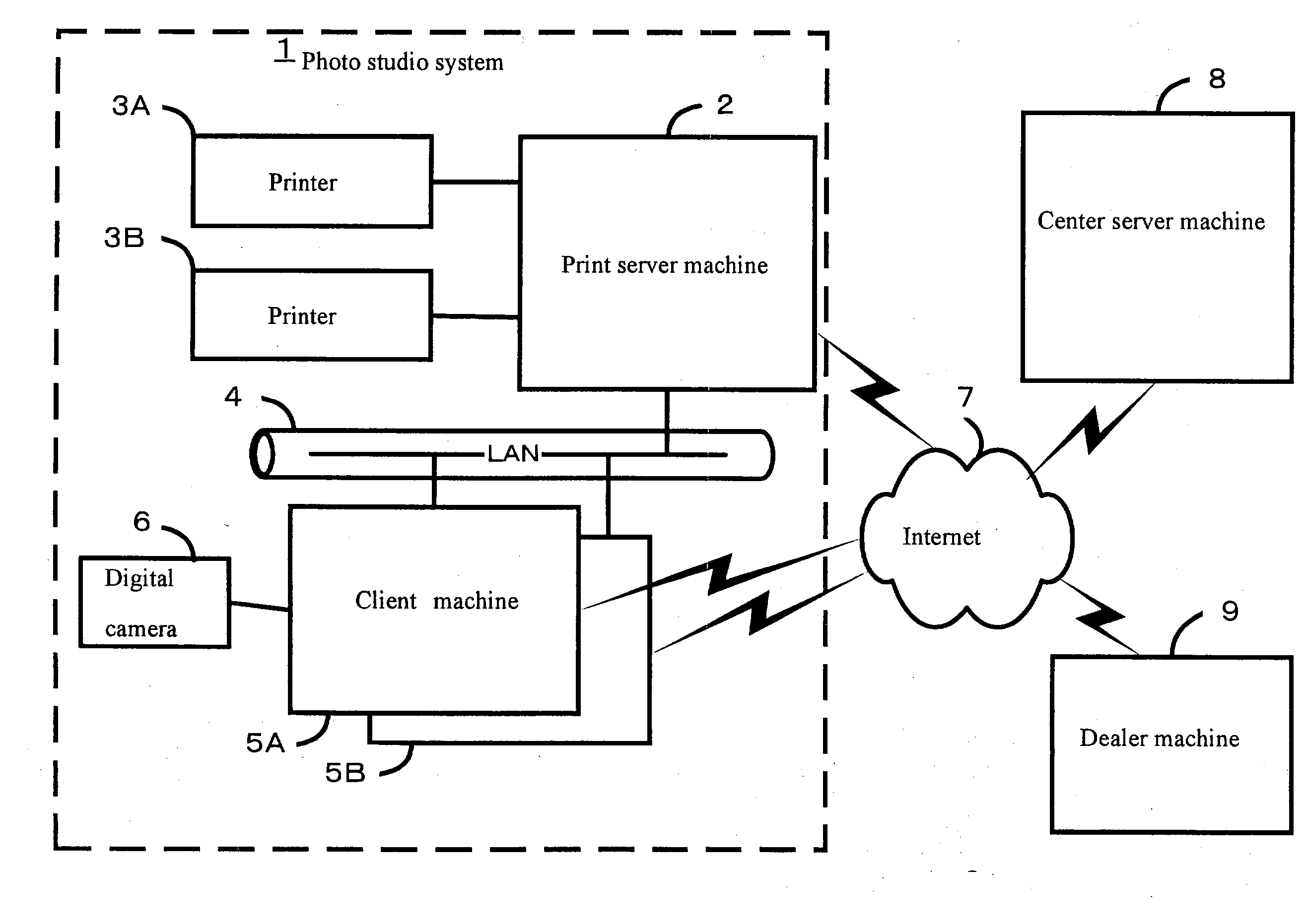
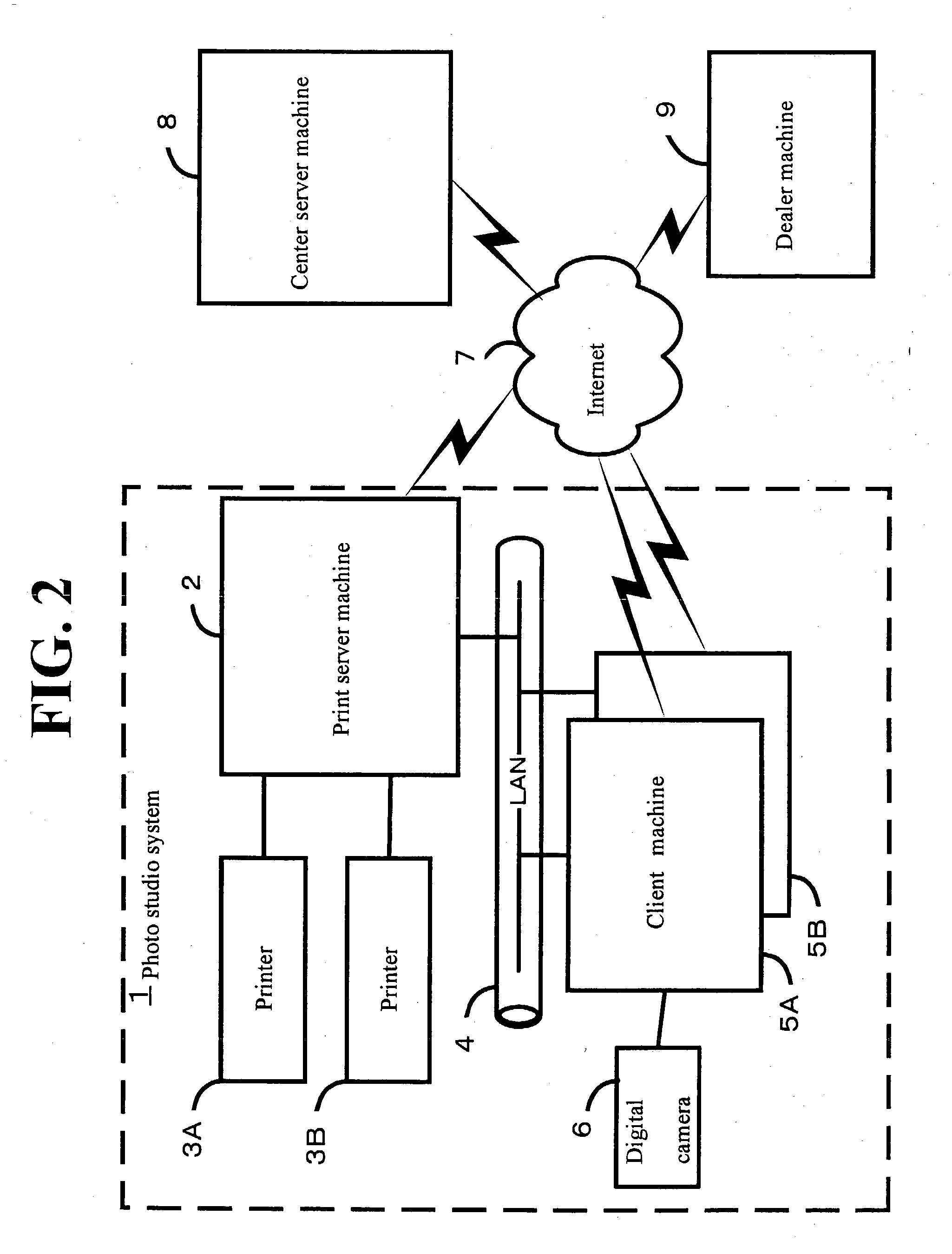
FIELD OF ART[0001] The present invention relates generally to a printing system employing computer(s) and electronic printer(s), and pertains more particularly to a printing system suited to operations, from the taking of photograph(s) to the printing thereof, taking place at photo studio(s).[0002] As a result of improvements in digital camera and electronic printer performance, not only amateurs but also photographic industry professionals have begun using digital cameras and electronic printers. Amateurs as well as professionals typically make use of a simple system wherein an electronic printer is connected by way of a dedicated interface cable, LAN, or the like to a personal computer on which a photo retouching program is installed. Use of a sophisticated photo retouching program makes it possible to carry out a diverse variety of retouching and / or color correction operations on photographic images taken with a digital camera, and / or freely vary the size and / or resolution of suc...

Claims


Application Information

Patent Timeline
IPC IPC(8): G06F3/12B41J21/00H04N1/00H04N1/387H04N1/60
CPCH04N1/00132H04N1/00137H04N1/00145H04N1/00161H04N1/603H04N1/00172H04N1/00188H04N1/387H04N1/00167
Inventor HATTA, ATSUSHITAKABAYASHI, NOBUHISAHOSHINO, MASARU
Owner SEIKO EPSON CORP
Learn More