Method and apparatus for manufacturing color filter substrate, method and apparatus for manufacturing electroluminescent substrate, method for manufacturing electro-optical device, and method for manufacturing electronic apparatus

a technology of color filter substrate and electroluminescent substrate, which is applied in the direction of optical filters, solid-state devices, chemical vapor deposition coatings, etc., can solve the problem of not being able to vertically erect the base member, and achieve the effect of high-quality color display

Inactive Publication Date: 2005-01-27
SEIKO EPSON CORP
View PDF1 Cites 11 Cited by
  • Summary
  • Abstract
  • Description
  • Claims
  • Application Information

AI Technical Summary

Benefits of technology

[0049] According to the method for manufacturing the electro-optical device of the present invention, it is possible to prevent foreign substances from being included inside the electro-optical device and to perform high-quality color display. Therefore, according to the method for manufacturing the electronic apparatus of the present invention which are achieved by the method for manufacturing the electro-optical device, it is possible to manufacture an electronic apparatus having a high-quality displaying unit.

Problems solved by technology

Also, in a conventional spin coating method, it is not possible to vertically erect the base member.

Method used


Image

  • Method and apparatus for manufacturing color filter substrate, method and apparatus for manufacturing electroluminescent substrate, method for manufacturing electro-optical device, and method for manufacturing electronic apparatus
  • Method and apparatus for manufacturing color filter substrate, method and apparatus for manufacturing electroluminescent substrate, method for manufacturing electro-optical device, and method for manufacturing electronic apparatus
  • Method and apparatus for manufacturing color filter substrate, method and apparatus for manufacturing electroluminescent substrate, method for manufacturing electro-optical device, and method for manufacturing electronic apparatus

Examples


first embodiment

OF METHOD FOR MANUFACTURING ELECTRO-OPTICAL DEVICE

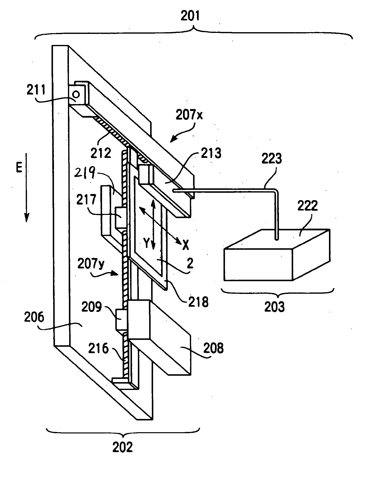
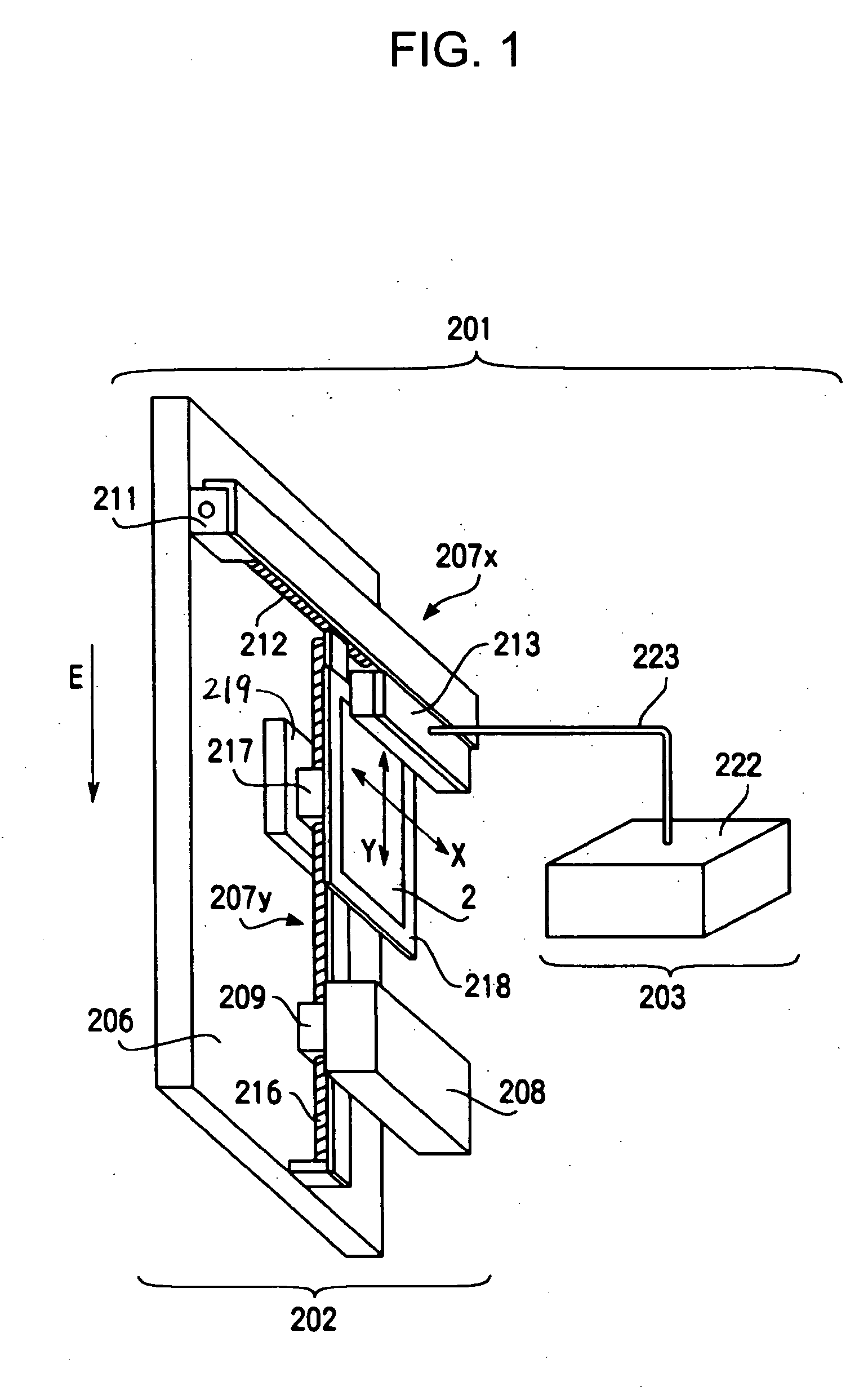
[0129] An embodiment of a method for manufacturing an electro-optical device according to the present invention will now be described with reference to a liquid crystal device that is an example of the electro-optical device. The present invention is not limited to the embodiment. FIG. 10 illustrates a transflective liquid crystal device, as an embodiment of a liquid crystal device, in which reflective display and transmissive display are selectively performed and a simple matrix method where switching elements are not used is employed.

[0130] A liquid crystal device 51 illustrated in FIG. 10 is formed by providing an illuminating device 56 and a wiring line substrate 54 to a liquid crystal panel 52. The liquid crystal panel 52 is formed by attaching a first substrate 57a that is rectangular or square as seen from the direction of arrow A to a second substrate 57b that is rectangular or square as seen from the direction of arrow A us...

second embodiment

OF METHOD FOR MANUFACTURING ELECTRO-OPTICAL DEVICE

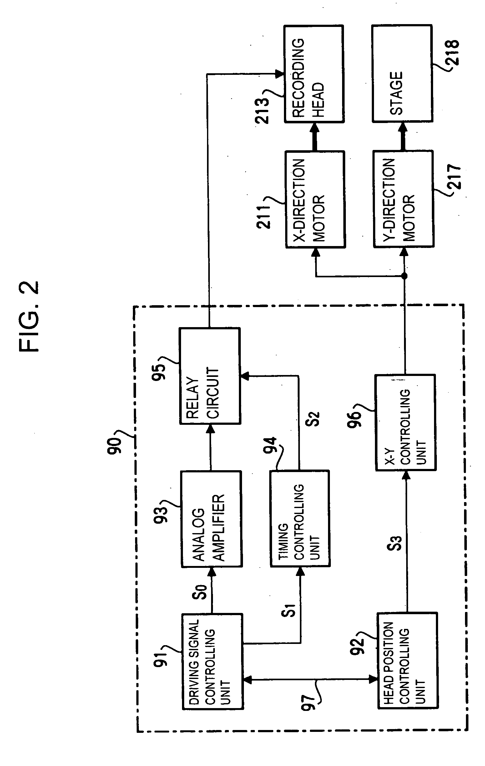
[0146] An embodiment of a method for manufacturing an electro-optical device according to the present invention will now be described with reference to an electroluminescent device that is an example of an electro-optical device. The present invention is not limited to such an embodiment. FIG. 17 illustrates an embodiment of the electric structure of an electroluminescent device. FIG. 16 illustrates a cross section of a part of the mechanical structure corresponding to the electric structure. Also, in the present specification, an electroluminescent substrate is a structure in which EL elements are formed on a substrate. The electroluminescent device is an electro-optical device in which a reflecting electrode or other optical components is provided on the electroluminescent substrate.

[0147] In FIG. 17, an electroluminescent device 101 includes a driving IC 107 for outputting data signals and a driving IC 108 for outputting scanning...


PUM

PropertyMeasurementUnit
angleaaaaaaaaaa
angleaaaaaaaaaa
diameteraaaaaaaaaa

Abstract

A method is provided for manufacturing a color filter substrate capable of preventing foreign substances from being attached to a base member. The method includes a step of discharging a liquid filter material from an inkjet head nozzle included in a recording head to the base member as liquid drops. In the discharging step, the liquid drops are discharged in a state where the base member is substantially vertically arranged. A color filter substrate manufacturing apparatus is preferably provided in a clean room that is maintained clean by an air current that flows from the top of the room to the bottom.

Description

RELATED APPLICATIONS [0001] This application claims priority to Japanese Patent Application No. 2003-156837 filed Jun. 2, 2003 which is hereby expressly incorporated by reference herein in its entirety. BACKGROUND [0002] 1. Technical Field of the Invention [0003] The present invention relates to an apparatus and a method for manufacturing a color filter substrate used for performing color display. The present invention also relates to an apparatus and a method for manufacturing an electroluminescent substrate in which light-emitting elements are formed on a substrate. The present invention also relates to a method for manufacturing an electro-optical device such as a liquid crystal device or an electroluminescent device. Furthermore, the present invention relates to a method for manufacturing electronic apparatuses, such as a mobile telephone, a portable information terminal, and a personal digital assistant (PDA). [0004] 2. Description of the Related Art [0005] Electro-optical devi...

Claims


Application Information

Patent Timeline
Patent Type & Authority Applications(United States)
IPC IPC(8): B05C5/00B05C13/02B05D1/26G02B5/20H01L51/00H01L51/40H01L51/50H01L51/56H05B33/10
CPCG02B5/201H01L51/56H01L51/0005H10K71/135H10K71/00A47J27/04A47J36/36A23L7/10A47J2027/043
Inventor KAWASE, TOMOMISHIMIZU, MASAHARU
Owner SEIKO EPSON CORP
Why Eureka
Try Eureka