Trolling motor assembly

a technology of motors and components, applied in the direction of propulsive elements, marine propulsion, vessel construction, etc., can solve the problems of time-consuming and inconvenient procedure, difficult to steer the boat, and extreme inconvenien

Inactive Publication Date: 2005-01-27
JOHNSON OUTDOORS
View PDF13 Cites 20 Cited by
  • Summary
  • Abstract
  • Description
  • Claims
  • Application Information

AI Technical Summary

Benefits of technology

[0008] One embodiment of the invention relates to a trolling motor assembly for use with a watercraft. The trolling motor assembly comprises a propulsion unit, a steering control unit configured to control the orientation of the propulsion unit, and a motor tube coupling the steering control unit to the propulsion unit. The motor tube includes a first tube section and a second tube section. The trolling motor assembly further comprises a mount system having a first portion adapted to be mounted to a watercraft and a second portion adapted to receive the motor tube, and an orientation system adapted to convert the trolling motor assembly between a first orientation and a second orientation. The orientation system includes an engagement device movable between a first engaged position, a disengaged position, and a second engaged position. The first engaged position corresponds to the first orientation, and the second engaged position corresponds to the second orientation.
[0009] Another embodiment of the invention relates to a trolling motor assembly for use with a watercraft. The trolling motor assembly comprises a propulsion unit, a steering control unit, a motor tube having a first tube section and a se...

Problems solved by technology

Although widely used, such trolling motors have several associated drawbacks.
Unfortunately, to orient the propulsion unit for backtrolling normally requires that the tiller or steering arm be extended away from the boat over the water.
As a result, it is extremely in...

Method used


Image

  • Trolling motor assembly
  • Trolling motor assembly
  • Trolling motor assembly

Examples


Embodiment Construction

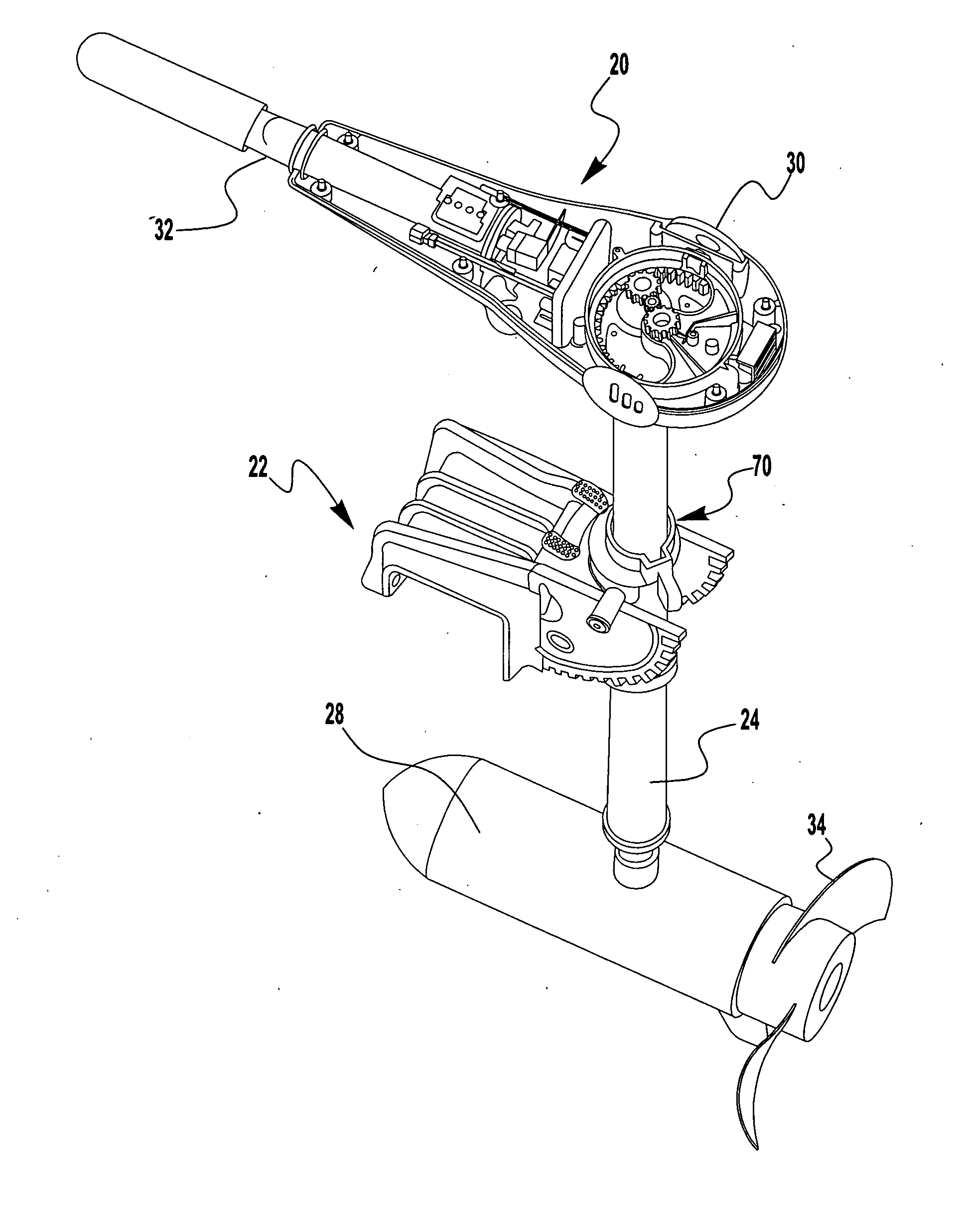
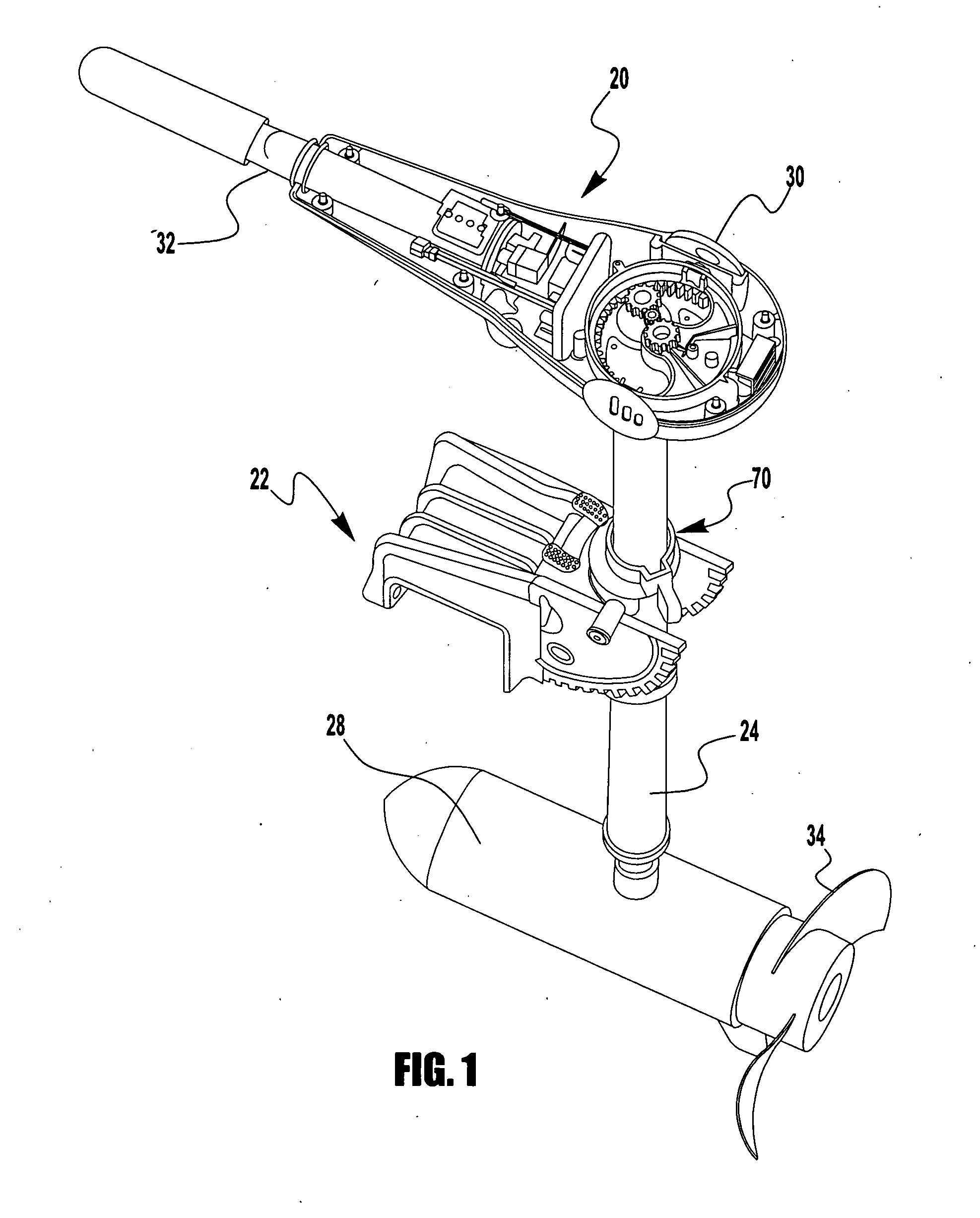
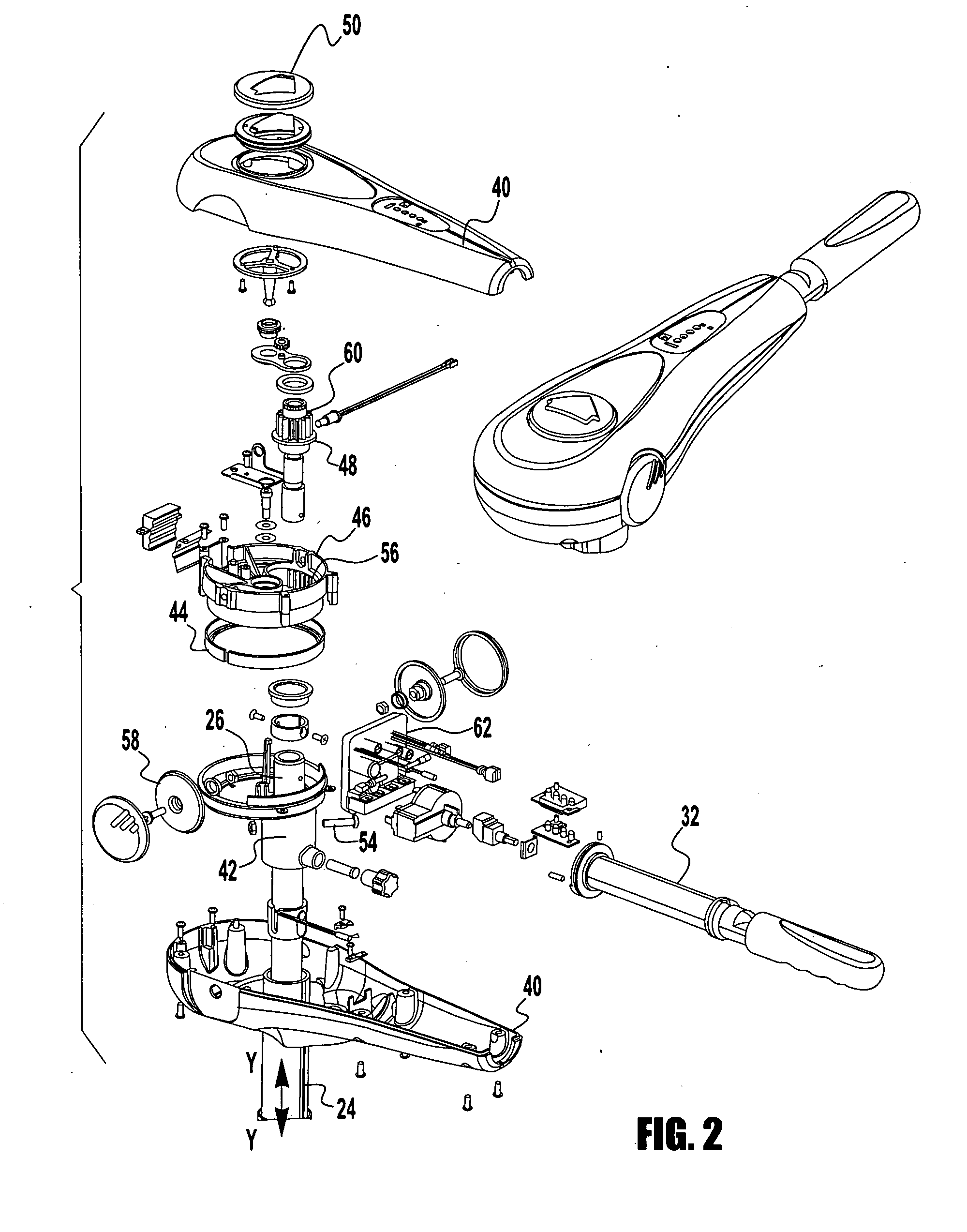
[0017]FIG. 1 is a perspective view of a trolling motor assembly 20 configured to be secured to a boat (not shown) at a location on the boat such as a bow or transom of the boat. Motor assembly generally includes boat mounting mechanism 22, an outer motor tube 24, an inner motor tube 26, a propulsion unit 28, a control unit 30 (such as a control box) and a steering control 32 (such as a handle). Mounting mechanism 22 is preferably secured (e.g., clamped) to the boat by a conventionally known clamping mechanism (not shown). Mounting mechanism 22 also enables propulsion unit 28 and control unit 30 to be rotated or pivoted relative to the boat (e.g., provide tilt adjustment for motor assembly 20).

[0018] Propulsion unit 28 comprises a conventionally known electric motor having a propeller 34. The motor rotatably drives propeller 34 to generate thrust used to move the boat. The amount of thrust generated by propulsion unit 28 may be altered by conventionally known methods such as using v...


PUM


Abstract

A trolling motor assembly for use with a watercraft is disclosed. The trolling motor assembly comprises a propulsion unit, a steering control unit, a motor tube, and a mount system having a first portion adapted to be mounted to a watercraft and a second portion adapted to support the propulsion unit. The assembly further comprises an orientation system is configured to re-index the trolling motor assembly between a forward troll position and a back troll position.

Description

CROSS-REFERENCE TO RELATED PATENT APPLICATIONS [0001] The present Application claims the benefit of priority, as available under 35 U.S.C. § 119(e)(1), to U.S. Provisional Patent Application No. 60 / 476,946 titled “Trolling Motor Assembly” filed Jun. 09, 2003 (which is incorporated by reference in its entirety).FIELD OF THE INVENTION [0002] The present invention relates to transom and bow-mounted outboard trolling motors for boats. In particular, the present invention relates to a trolling motor assembly that provides for reorientation or reconfiguration of a propulsion unit between a forward troll position and a back troll position. BACKGROUND OF THE INVENTION [0003] Outboard trolling motors have become extremely popular for low speed maneuvering of small boats. Their ability to slowly traverse the boat across an area without excessive noise or disturbance of the water has made such trolling motors especially popular with fishermen where fishing by trolling requires slow movement of...

Claims


Application Information

Patent Timeline
IPC IPC(8): B60L50/10B63H20/00
CPCB63H20/106B63H20/007
Inventor BERNLOEHR, DARREL A.
Owner JOHNSON OUTDOORS
Why Eureka
Try Eureka