Thermophoretic protection of reticles

a technology of reticles and thermophoretic protection, which is applied in the field of reticles protection, can solve the problems of insufficient mechanical protection methods to prevent small particles, and the effectiveness of removing such small particles is largely unproven

Inactive Publication Date: 2005-02-03
INTEL CORP
View PDF9 Cites 7 Cited by
  • Summary
  • Abstract
  • Description
  • Claims
  • Application Information

AI Technical Summary

Problems solved by technology

Current mechanical protection methods may be inadequate to prevent small particles from landing on the reticles.
If particles landing on the reticle are large enough to adversely af...

Method used


Image

  • Thermophoretic protection of reticles
  • Thermophoretic protection of reticles

Examples


Embodiment Construction

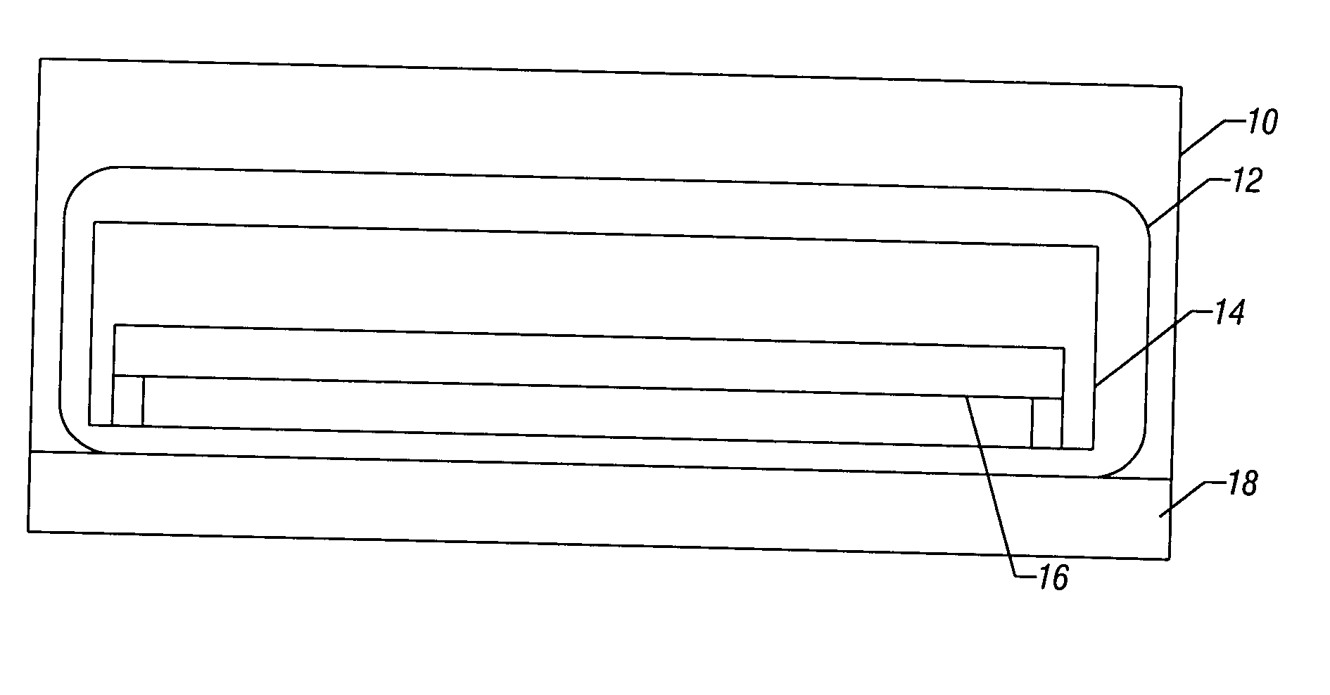
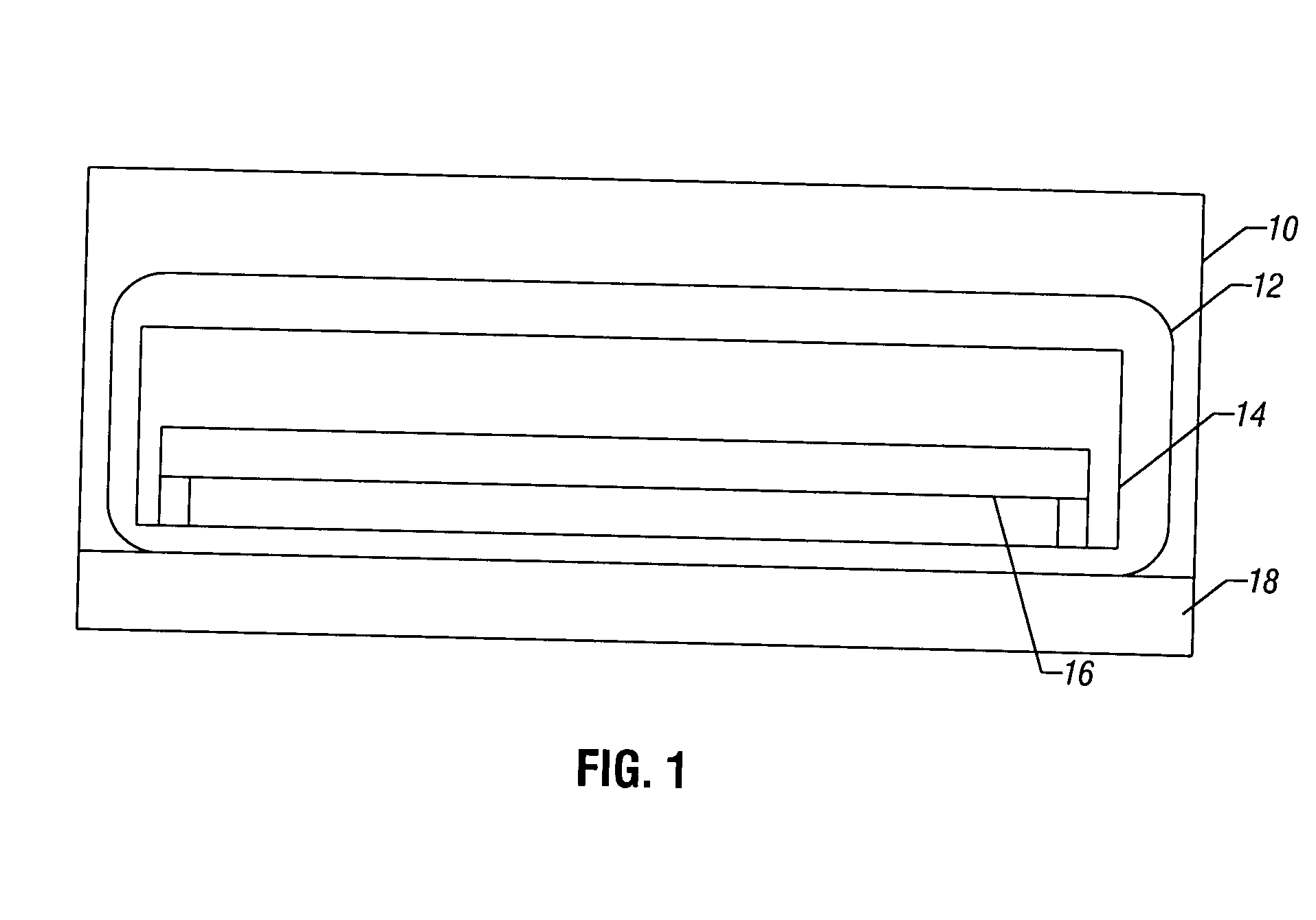
[0009] Referring to FIG. 1, a shipping box 10 may enclose one or more packages 12. Each package 12 may, in one embodiment, be an antistatic bag that carries one or more reticle carriers 14. Each reticle carrier 14 may contain one or more reticles 16.

[0010] Also included within the box 10 is a self-contained thermophoretic source 18. By self-contained, it is intended to refer to the fact that a power supply is not needed. It is desirable to make the thermophoretic source 18 self-contained to facilitate transport of the box 10.

[0011] Thermophoresis is a process whereby particles are attracted to colder temperatures and repelled from warmer temperatures. Thus, particles inside the package 12 will be attracted to the thermophoretic source 18 and away from the reticle 16.

[0012] Thermophoresis is a non-continuum effect. The gas mean free path must be comparable or larger than the particle diameter for thermophoresis to occur. A temperature gradient causes a particle motion away from hi...


PUM


Abstract

A thermophoretic source may be contained within the packaging of a reticle during transport or otherwise to protect the reticle from particle contamination. For example, in advanced lithography technologies, very small particles may be thermophoretically attracted away from the reticle during transport so that cleaning on arrival may not be necessary in some cases.

Description

BACKGROUND [0001] This invention relates generally to protecting reticles from particle contamination, for example during transportation. [0002] Reticles are patterned devices that can be exposed to transfer a pattern on the reticle to a semiconductor structure. Through the use of reticles, patterns may be repeatedly transferred to semiconductor structures in an automated process. This greatly reduces the cost of forming integrated circuits. [0003] Reticles are transported in a shipping container. Physical protection is provided by a shipping box. The reticle carrier that actually carries the reticle may be contained within an antistatic bag. [0004] Conventional packaging is sufficient for optical reticles whose minimum printable particle size is roughly 30 microns. In such case, any particle smaller than 30 microns would not adversely affect the operation of the reticle. [0005] However, with certain advanced lithography reticles, such as extreme ultraviolet (EUV) reticles, the tech...

Claims


Application Information

Patent Timeline
IPC IPC(8): B65D85/30G03F7/20H01L21/673
CPCG03F1/66G03F7/70741H01L21/67393H01L21/67359G03F7/70875
Inventor GOLDA, JANICE M.
Owner INTEL CORP
Why Eureka
Try Eureka