Caulking gun

Active Publication Date: 2005-02-03
RUMRILL TRUSTEE VALERIE E +1
View PDF10 Cites 39 Cited by
  • Summary
  • Abstract
  • Description
  • Claims
  • Application Information

AI Technical Summary

Benefits of technology

[0021] The rearward end of the caulking gun barrel is shaped in a configuration which mates with the forward end of the handgrip portion. To this end, the rearward portion of the barrel is shaped with a circumferential inwardly projecting lip extending approximately 180° about the center opening in a U-shaped configuration. This U-shaped lip engages the outwardly projecting lip of the handgrip portion by receiving the flat round disk in an interlocking configuration until the two components are fully engaged. The lip on the barrel slides over the lip on the handgrip portion and is locked in place with the insertion of the push rod. This makes for easy assembly without requiring additional hardware and allows the barrel to be rotated relative to the handgrip portion. The friction feel of the rotation is accomplished by using different material hardness for the handgrip portion and the barrel. For example, in one preferred embodiment, the lip and flat attachment member of the handgrip portion is fabricated of fiber reinforced nylon, whereas the lip and adjacent surface of the barrel portion is made of polypropylene or polyethylene. Assembly of the gun is completed by placing a pusher plate on the forward end of the push rod end securing it in place with a nut threaded onto the end of the push rod. The caulking gun may then be operated in a conventional manner, with repetitive squeezes of the trigger mechanism ratcheting the push rod forward to cause material to be extruded from the caulk tube. This construction advantageously permits the barrel and caulk tube to be rotated as desired, relative to the handgrip portion, for better placement of the nozzle when extruding caulking material.
[0022] The handgrip portion itself is formed with a number of features which constitute improvements over prior art caulking guns. A thumb operable lever is positioned on the top side of the handle so that a drip/no drip position can be easily selected. Position

Problems solved by technology

However, some types of caulking material for proper application require a continued pressure against the back plate even when the trigger is not being pulled, i.e., the ratchet type of mechanism.
This do

Method used


Image

  • Caulking gun
  • Caulking gun
  • Caulking gun

Examples


Example

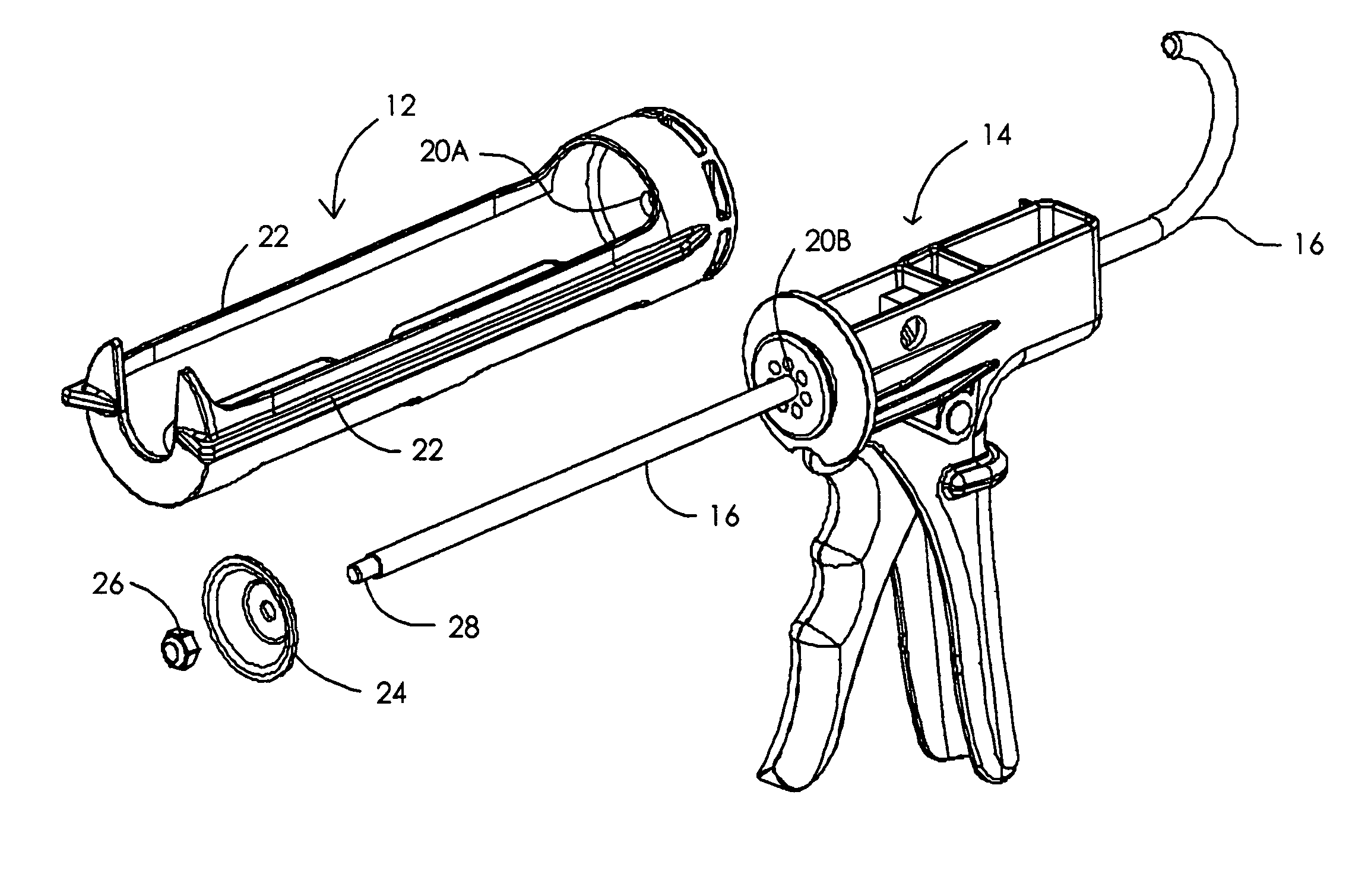
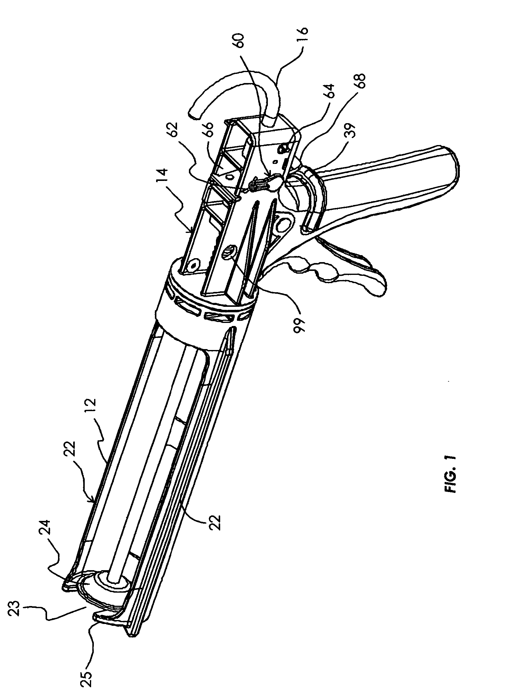
[0039] As shown in the drawings and with particular reference to FIG. 1, a preferred embodiment 10 is shown comprising a barrel-shaped tube housing 12 and a handgrip portion or trigger housing 14. The barrel-shaped tube housing 12 is cut away along the side walls 22 to provide easy access for inserting a caulk tube into the tube housing. The elements 22 are reinforcing nibs which are mounted lengthwise along the outside of the tube housing 12 to add stiffness and support for the tube housing, particularly for the edge portions of the half-cylinder. Another pair of reinforcing ribs below the elements designated 22 provide reinforcement for the tube housing at the location of the lower central cutout shown in FIG. 7.

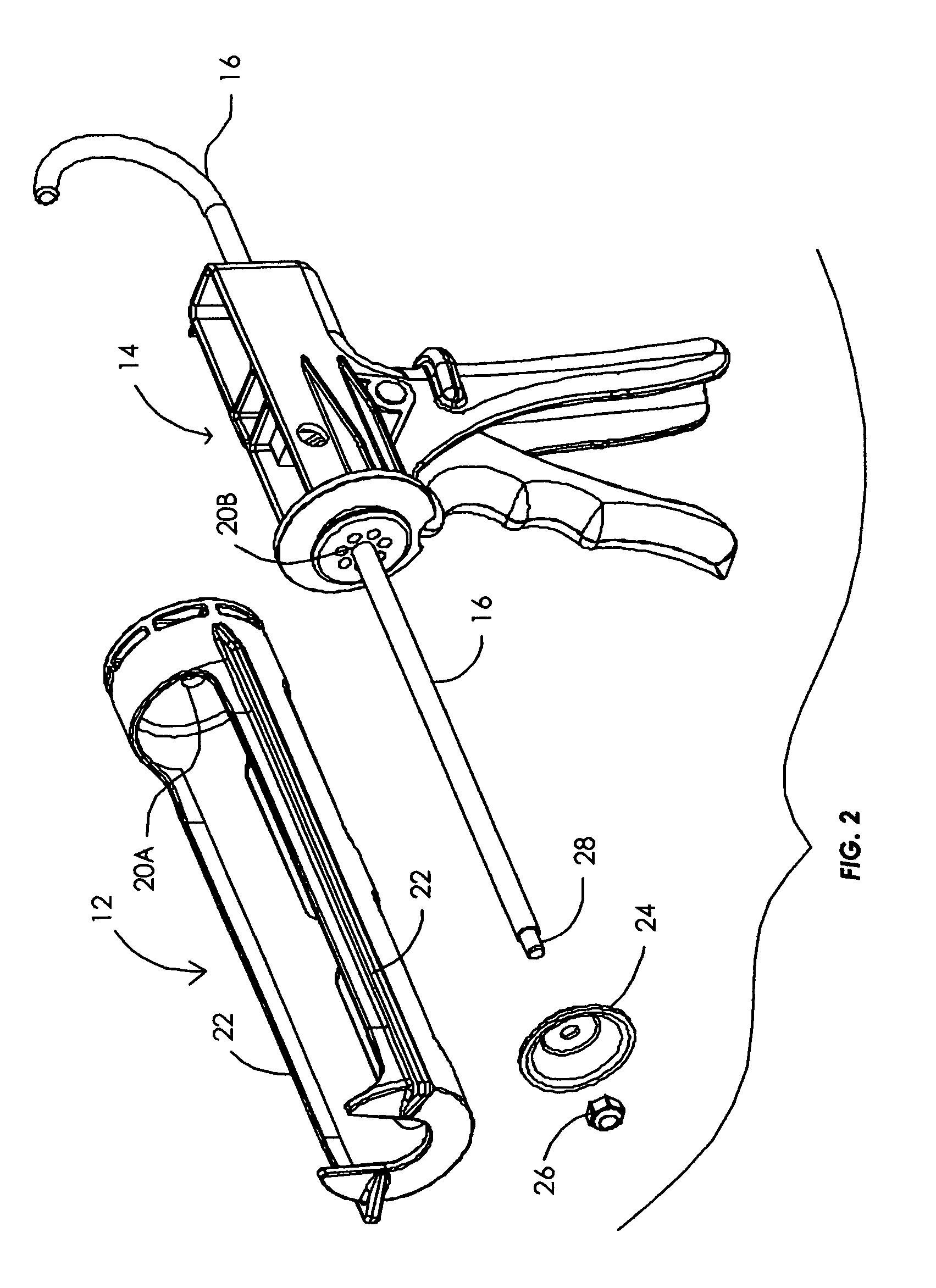
[0040] Also shown in FIG. 7 (as well as in FIG. 2) are a pair of triangular sections 27 which are placed at the forward end of the tube housing 12 to provide reinforcement for the forward wall 25 where it attaches to the tube housing.

[0041] Passing through these two hous...


PUM


Abstract

A caulking gun for dispensing caulking material from a standard caulk tube. The gun is fabricated in three basic parts; a trigger assembly, a trigger housing and a barrel cage for holding the tube. The facing portions of the barrel cage and trigger housing is provided with a mating configuration which enables the gun to be easily assembled for use and easily disassembled for storage in a toolbox. A novel drip/no drip feature is provided wherein a cam actuator conveniently positioned on the trigger housing enables an operator to select between no drip operation or drip type operation when caulking material and application requirements warrant such. A thumb release mechanism is provided on the rear of the trigger housing so the operator can release the driving rod for insertion of another tube of caulk when the unit has been placed in the drip position.

Description

[0001] This application claims the benefit of U.S. Provisional Application No. 60 / 491,353, filed Jul. 31, 2003.BACKGROUND OF THE INVENTION [0002] 1. Field of the Invention [0003] The invention relates to hand-held material-dispensing devices such as caulking guns and, more particularly, to a specific type of construction for caulking guns. [0004] 2. Description of the Related Art [0005] Hand-held material dispensing devices are well known in the art and generally rely on the action of a piston to push fluid out of a receptacle toward the application area. The movement of the piston is induced by the advancement of a piston rod in the direction of the receptacle, with the piston rod being advanced in the direction of travel by the operator's squeezing of a trigger in engagement therewith. [0006] One such fluid dispenser is disclosed in U.S. Pat. No. 4,461,407 to Finnegan. The Finnegan patent incorporates an automatic pressure release mechanism such as is typical in many caulking guns...

Claims


Application Information

Patent Timeline
IPC IPC(8): B05C17/01B67D7/60B67D99/00
CPCB05C17/01B05C17/0143B05C17/0123
Inventor RUMRILL, DANNYCHILDS, LARRY C.
Owner RUMRILL TRUSTEE VALERIE E
Why Eureka
Try Eureka