LED drive for generating constant light output

a technology of led traffic devices and constant light output, which is applied in the direction of identification means, instruments, signalling systems, etc., can solve the problems of reducing the effective light output reducing the usable life of led traffic devices, and having a specific disadvantag

Active Publication Date: 2005-02-03
UNIVERSAL LIGHTING TECHNOLOGIES
View PDF10 Cites 66 Cited by
  • Summary
  • Abstract
  • Description
  • Claims
  • Application Information

AI Technical Summary

Benefits of technology

[0007] Accordingly, one object of the present invention is to provide a device that can be used with an LED traffic device to compensate for the reduction of effective light output causes by degradation in the plastic lens used with this device.
[0008] Another object is to provide a device that can be used to compensate for the reduction in effective light output in LED light sources that may be caused by other reasons as well.

Problems solved by technology

In addition, LED traffic devices have longer usable life spans when compared to their incandescent traffic device counterparts.
LED traffic devices, however, do have one specific disadvantage that is addressed by the present application.
This lens degrades over time and, as a result, reduces the effective light output of these devices.
This is an undesirable condition because it makes it difficult for automobile drivers to see the traffic signals generated by the LED traffic device.
A review of the prior art relating to LED traffic devices indicates that there does not appear to be any suitable solution to this problem.

Method used


Image

  • LED drive for generating constant light output
  • LED drive for generating constant light output
  • LED drive for generating constant light output

Examples


Embodiment Construction

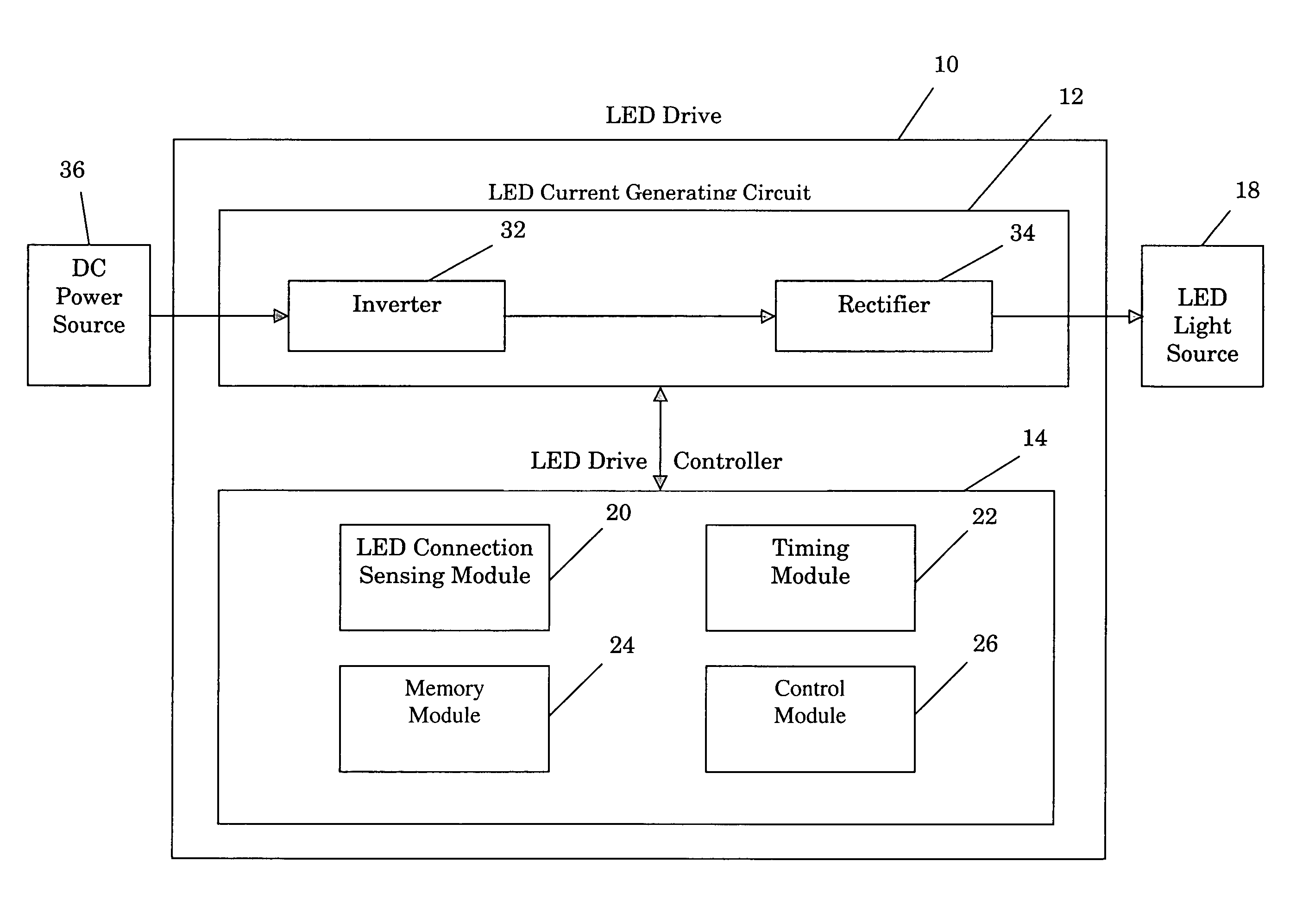
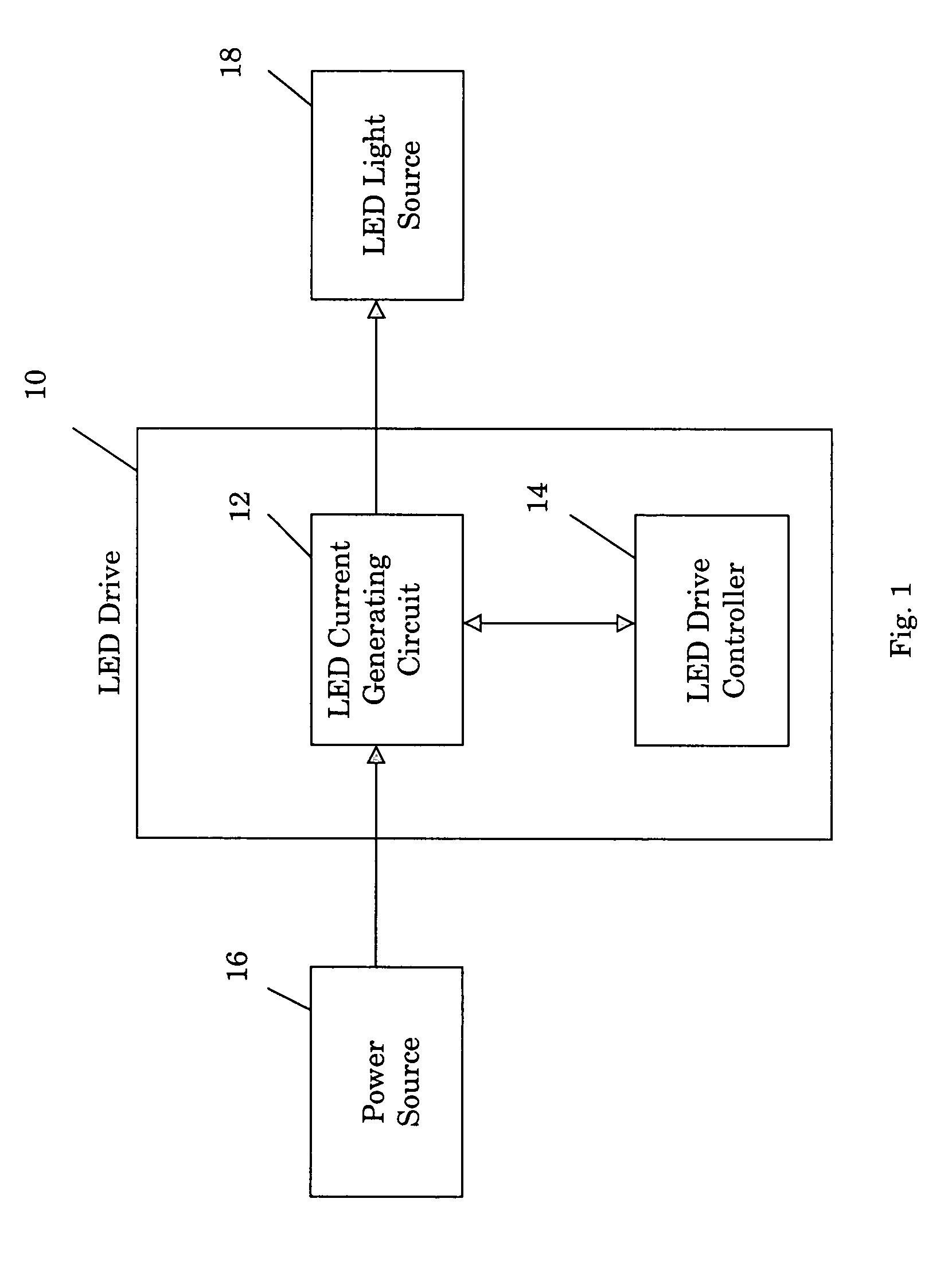
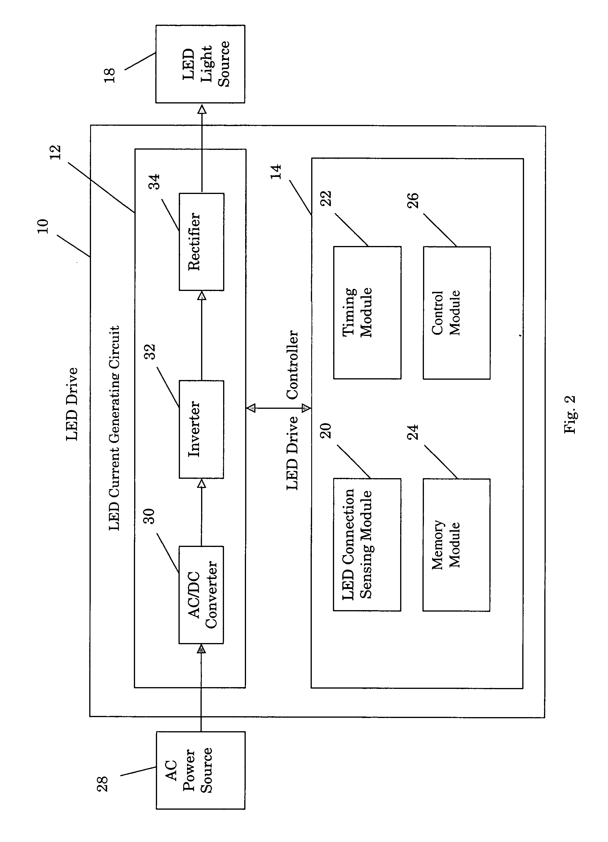
[0017] Referring to FIG. 1, one embodiment of the light emitting diode (LED) light source drive 10 (referred to simply as the LED drive 10) of the present invention includes an LED current generating circuit 12 and an LED drive controller 14. The LED current generating circuit 12 may also be referred to as an LED voltage supply, an LED power converter, an LED current converter, or an LED current generator. In a similar manner, the LED drive controller 14 may alternatively be referred to as an LED voltage controller, an LED current controller, an LED power controller, or simply an LED controller.

[0018] The LED drive 10 is adapted to be connected to and to receive power from a power source 16 and to be connected to and output a current signal to an LED light source 18. More specifically, the LED current generating circuit 12 is adapted to receive power from the power source 16 and to convert that power into a power signal (also referred to as an output voltage signal) that can be app...


PUM


Abstract

An LED light source drive includes an LED current generating circuit and an LED drive controller. The current generating circuit is operable to receive power from a power source and to generate a dc current that can be used to the drive an LED light source. The drive controller is operable to control the dc current to ensure that the light output of the light source remains approximately constant over its operating lifetime. In one embodiment, the drive controller ensures that the effective light output of the light source remains approximately constant by automatically increasing the dc current in predetermined amounts at predetermined times. In an alternative embodiment, the drive controller includes an LED light sensor that is operable to generate a light signal indicative of the effective light output of the light source and the controller uses this light signal to control the dc current output.

Description

BACKGROUND OF THE INVENTION [0001] The present invention relates generally to devices that can be used to control the light output of light sources. More particularly, this invention pertains to a device that can be used to control the light output of a light emitting diode light source. [0002] Light emitting diode (LED) light sources are known in the art. For example, the prior art teaches the use of LED traffic signal devices. These devices are typically designed to be connected to an ac power source and include an ac to dc converter that converts the ac power supplied to the device into dc power. This dc power is then used to power an array of LEDs included in the device. [0003] The various benefits of LED based traffic devices are well known in the art. LED traffic devices consume less power than their incandescent traffic device counterparts. In addition, LED traffic devices have longer usable life spans when compared to their incandescent traffic device counterparts. [0004] LE...

Claims


Application Information

Patent Timeline
Patent Type & Authority Applications(United States)
IPC IPC(8): H01K7/04H01L27/15H05B37/02H05B44/00
CPCH05B33/0851H05B33/0815H05B45/39H05B45/12
Inventor SHACKLE, PETER W.
Owner UNIVERSAL LIGHTING TECHNOLOGIES
Why Eureka
Try Eureka