Image capture and display device

a display device and image capture technology, applied in the field of electronic image capture and display devices, can solve the problems of compromising the “mirror-like” function of the unit, the interface with the touch screen located between the user and the beam splitter is not satisfactory, and the solution is not very satisfactory

Inactive Publication Date: 2005-02-03
MONUMENT PEAK VENTURES LLC
View PDF3 Cites 66 Cited by
  • Summary
  • Abstract
  • Description
  • Claims
  • Application Information

AI Technical Summary

Benefits of technology

[0014] providing a display panel that can be alternately placed in a first display state and a second transmissive state, said display panel when in said first display state allows an image to be displayed on said display panel and when placed in said second transmissive state allows transmission of an image of an object through said panel;

Problems solved by technology

The problem with this technique is that the displayed image appears to be located at a distance behind the beam splitter, compromising the “mirror-like” function of the unit.
It is well known and desirable to use a touch screen as a means for providing an interface between a user and a display device such as a CRT, however with the arrangement described by Andrews et al., the interface with a touch screen located between the user and the beam splitter does not provide a satisfactory feel, since when the subject places her finger on the touch screen, the image of the subject's finger does not appear to be located at the screen, rather it appears to be displaced to the rear of the screen.
This is not a very satisfactory solution.
The problem with this arrangement is that the highly transparent surface allows the user to directly view the projection lens of the image projection apparatus.
Another problem in the prior art is the ability to capture an image of person on the same optical axis on which the person is viewing a display device.
The problem with the described situation is that the person viewing the display while being recorded by an off-axis camera appears to fail to make eye contact with the recording camera and whoever may be viewing that image.
There is a similar problem with an individual using a teleprompter.

Method used


Image

  • Image capture and display device
  • Image capture and display device
  • Image capture and display device

Examples


Embodiment Construction

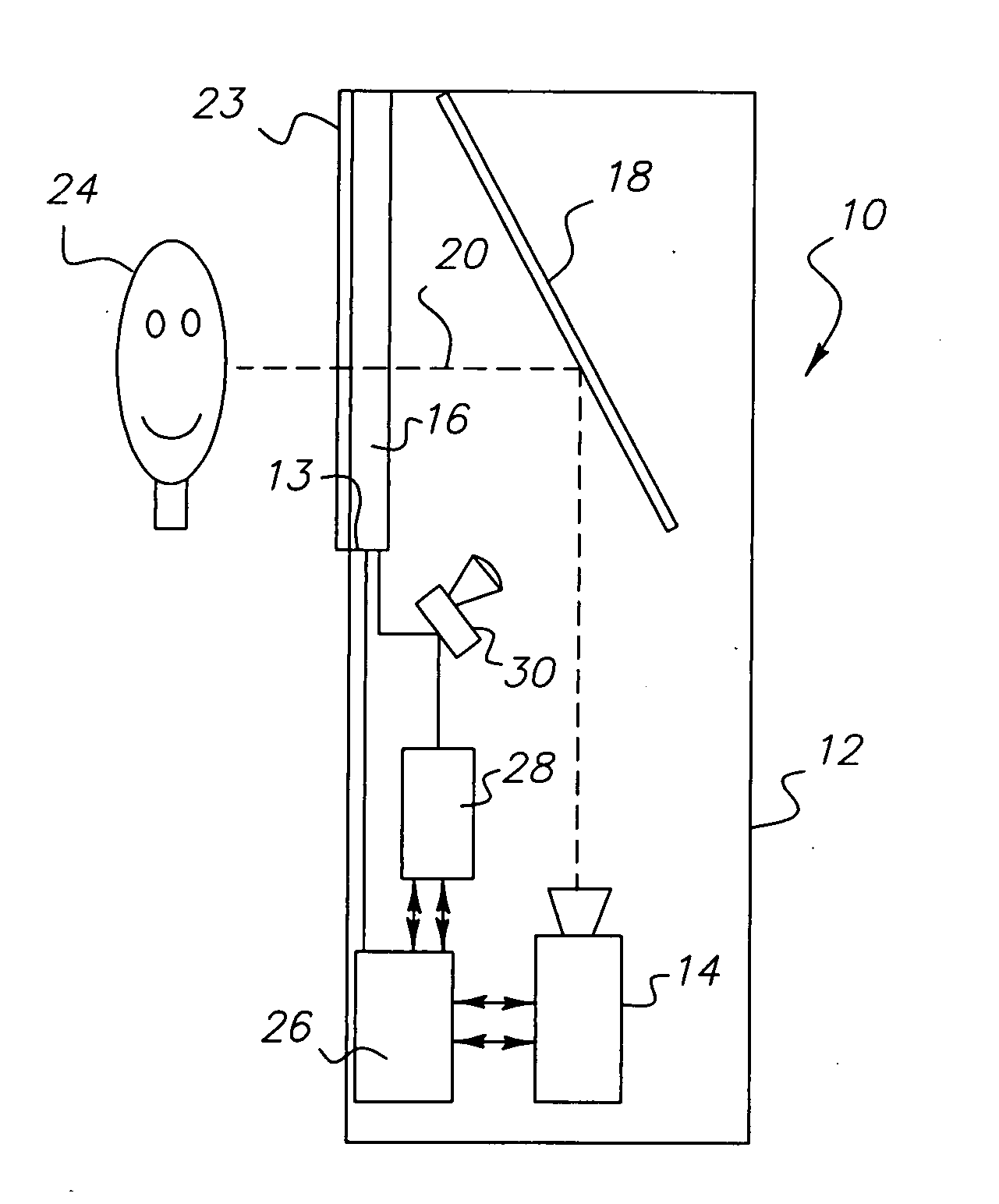
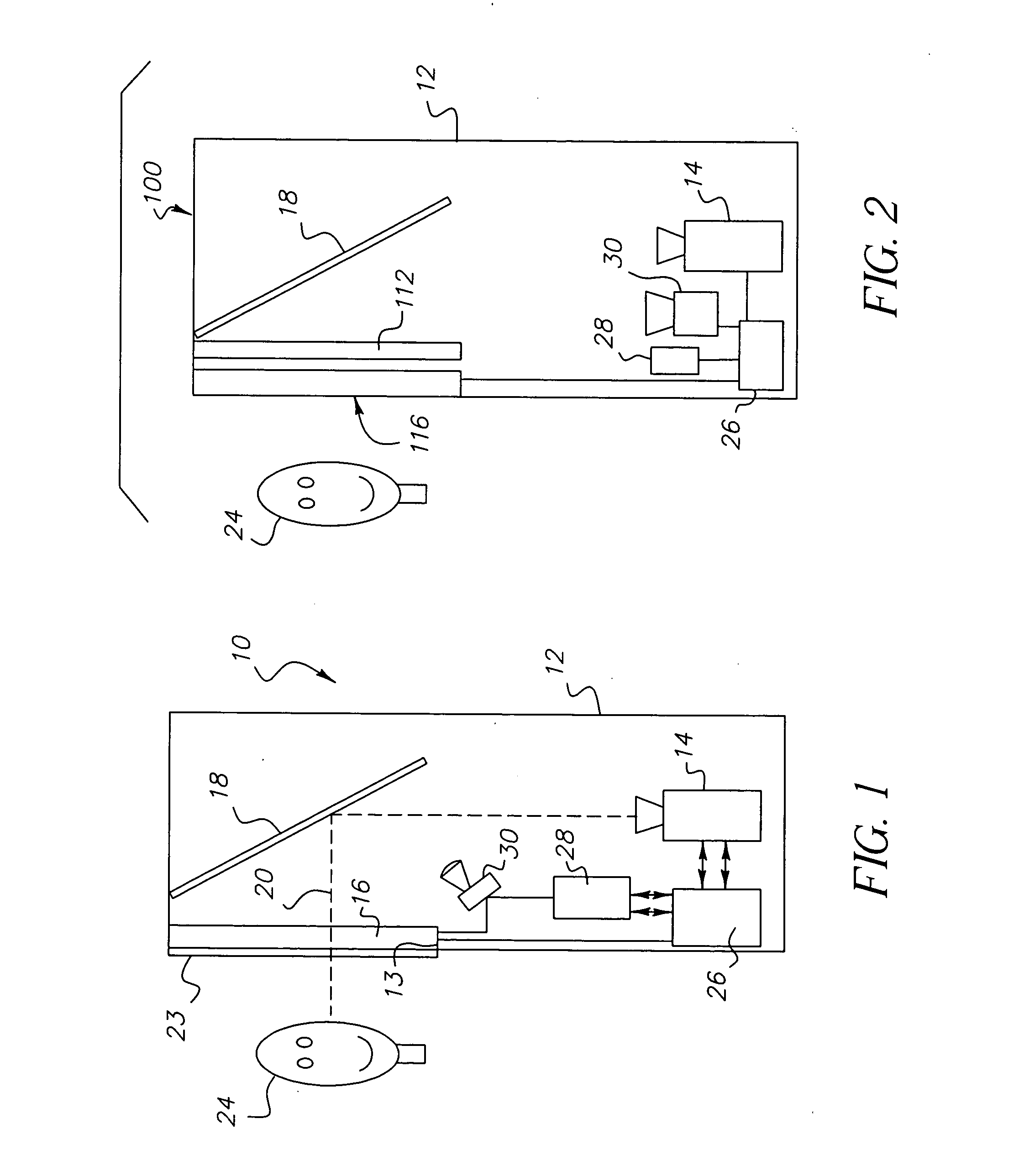
[0029] Referring to FIG. 1, the image capture and display device, generally designated 10, according to the present invention is housed for example in a cabinet 12. It will be understood that the capture and display device may be a component of a larger device such as a photobooth (not shown). An electronic camera 14 such as a KODAK DIGITAL SCIENCE DVC323 Digital Video Camera available from the Eastman Kodak Company, Rochester, New York, and a display panel 16 such as an OLED panel available from the Eastman Kodak Company, Rochester, New York, are located in the cabinet 12 with respect to an optical element such as a fully silvered mirror 18 in a known manner such that they share a common optical axis 20. The display panel 16 is positioned in a front opening 13 of the cabinet 12. Display panel 16 is electronically switchable between a first state and a second state. Display panel 16 may comprise for example a matrix of Organic Light Emitting Diodes that change state when an electric...


PUM


Abstract

A display device for capturing and displaying images along a single optical axis. The device includes a display panel having a front side and a back side, said display panel capable of being placed in a first display state which allows displaying of an image on said front side for viewing of an image and a second transmissive state wherein said display panel becomes substantially transmissive so as to allow capture of an image of an object positioned in front of said front side of said display panel. An image capture device is provided for capturing said objective image through said display panel when said display device is in the second transmissive state. An image supply source is provided for providing an image to said display panel when said display panel is in said first display state and a mechanism for alternating placing said display panel between said first display state and second transmissive state such that an image can be viewed on said display screen and said object can be captured in a manner such that said alternating between said first display state and said second transmissive state is substantially imperceptible to a user of said display panel.

Description

CROSS REFERENCE TO RELATED APPLICATIONS [0001] This is a Continuation-in-Part of application Ser. No. 10 / 264,058 filed Oct. 3, 2002 which is a continuation of application Ser. No. 09 / 452,091 filed Nov. 30, 1999 (abandoned).FIELD OF THE INVENTION [0002] The present invention relates to an electronic image capture and display device, and in particular an image capture and display device of the type employing an electronic camera to capture an image of a subject and an electronic image display device to display images. BACKGROUND OF THE INVENTION [0003] U.S. Pat. No. 4,864,410, issued Sep. 5, 1989 to Andrews et al., illustrates a technique using a beam splitter, electronic camera, and a video display (CRT) to simultaneously capture and view a subject on the same optical axis similar to the function of a conventional optical mirror. The images captured by the camera can be processed prior to display to provide special effects such as the distortions employed in a fun-house mirror. The p...

Claims


Application Information

Patent Timeline
Patent Type & Authority Applications(United States)
IPC IPC(8): H04N5/74
CPCH04N9/3176H04N9/3141
Inventor FREDLUND, JOHN R.MANICO, JOSEPH A.KERBS, ROBERT E.
Owner MONUMENT PEAK VENTURES LLC
Why Eureka
Try Eureka