Investigation of destroyed assemblies and identification of components thereof

Active Publication Date: 2005-02-03
THE BOEING CO
View PDF6 Cites 16 Cited by
  • Summary
  • Abstract
  • Description
  • Claims
  • Application Information

AI Technical Summary

Benefits of technology

[0007] The present invention eliminates many of the disadvantages associated with investigations of destroyed assemblies by eliminating the need to perform many of the steps previously required during the reconstruction of such assemblies. Despite the elimination of such steps, the invention nonetheless provides the benefits associated with such prior art reconstructions. In general, the invention provides a means for identifying component parts quickly and relatively easily and provides a means for digitally rigging the component parts in three-dimensional virtual space, thereby minimi

Problems solved by technology

In some situations, aircraft crashes in particular, locating the components can be a difficult task due to the fact that such components are often spread out over a very large area.
As a result of the difficulties associated with locating such components, invariably many components are never located.
Thus, the task of identifying the located components can, in itself, be tedious and time consuming.
However, the rigging of the components can be difficult and expensive due to the fact that unique structure is often required to support the components in their relative positions.
In some cases, the cost of the structure supporting the rigging, alone, can be extensive.
Moreover, rigging often limits the mobility o

Method used


Image

  • Investigation of destroyed assemblies and identification of components thereof
  • Investigation of destroyed assemblies and identification of components thereof

Examples


Example

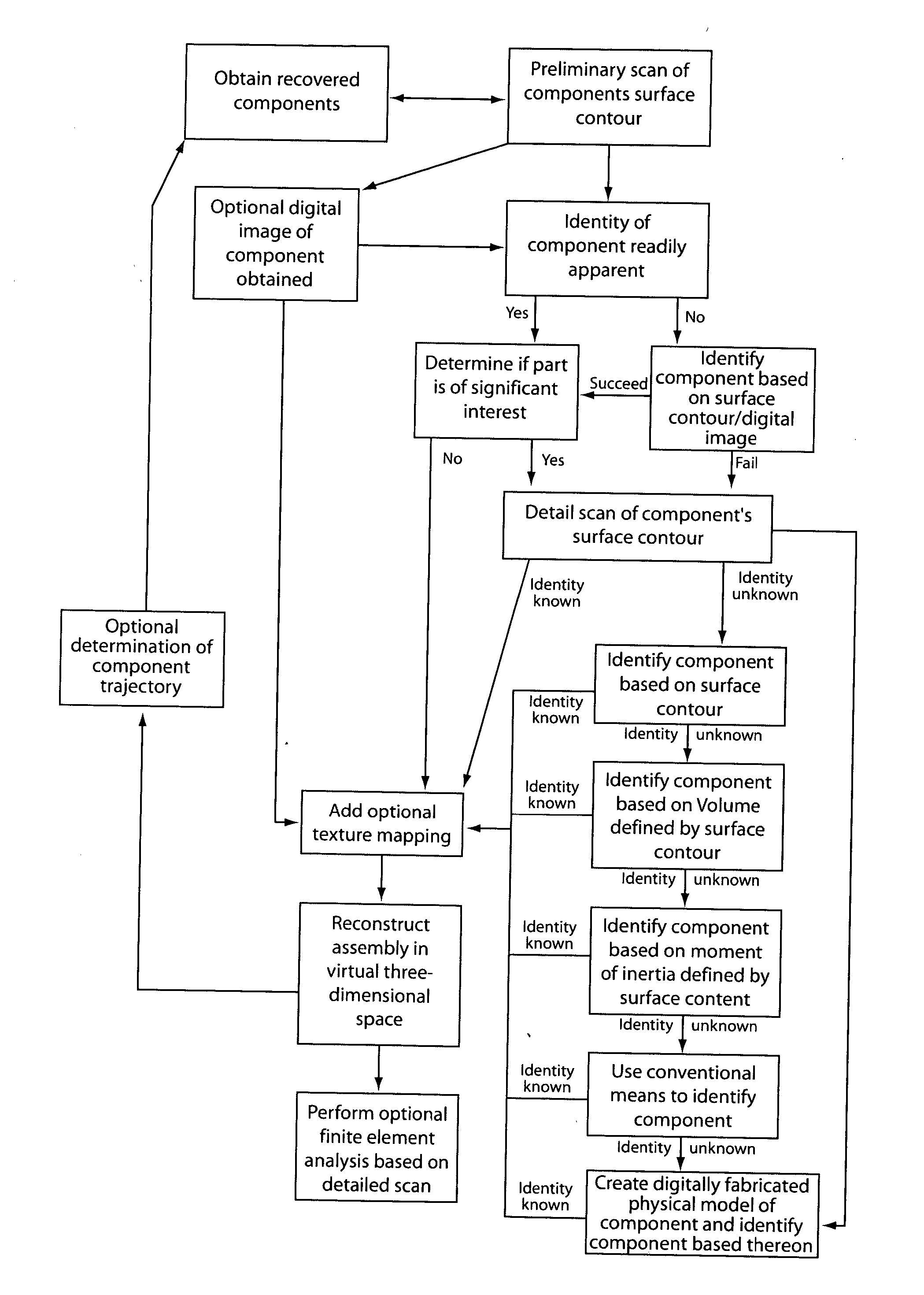
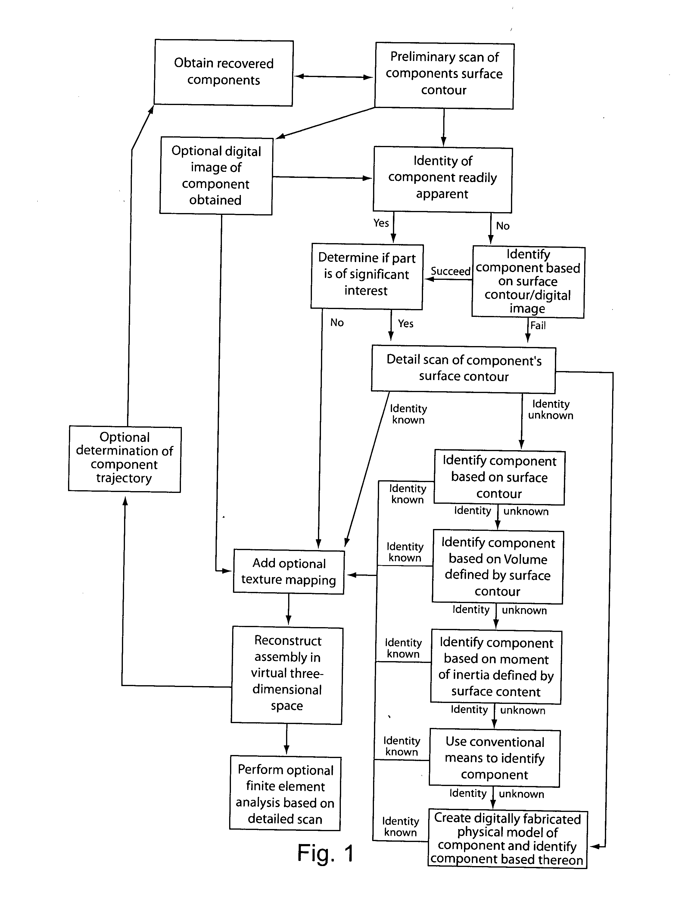
[0012] A flow chart of the preferred method of practicing the invention is shown in FIG. 1 and is particularly adapted for the investigation of a destroyed aircraft. For purposes of describing the preferred method, it should be appreciated that such an aircraft is presumed to have been disassembled into a plurality of component parts as a result of an unknown cause of destruction. Furthermore, at least some of the components of the originally assembled aircraft are presumed to be recoverable.

[0013] In general, the preferred method begins by obtaining components of a disassembled assembly. Preferably, these components are transported to a central location from the locations where they were first located after being separated from the assembly. However, because the preferred method of practicing the invention does not necessarily require physical rigging of the components in an effort to partially reconstruct the assembly, relocation of the components is not necessarily required.

[00...


PUM


Abstract

A method is disclosed for providing a means for identifying recovered component parts of a destroyed assembly quickly and relatively easily using digital or electronic scanning techniques and comparison to virtual components that are presumed to have constituted the original assembly. The method also provides a means for digitally rigging the component parts in three-dimensional virtual space, thereby minimizing and, in some situations, possibly eliminating any need to physical rig the component parts.

Description

BACKGROUND OF THE INVENTION [0001] This invention pertains to methods of investigating accidents or intentional acts leading to the destruction of assemblies. In particular, this invention pertains to the identification of components that previously formed part of an assembled object and to a method of investigating the cause of the destruction of the assembly. [0002] In situations such as an investigation of the cause of an aircraft crash, a detailed reconstruction of the events leading up to the destruction of the aircraft is often conducted. In addition to recorded data and witness knowledge, the recovered components of the aircraft are often useful in identifying the cause of the crash and, in the cases where no recorded data and witness knowledge is available, scrutiny of such components may be the only means of conducting an investigation. [0003] The analysis of the components of a destroyed assembly, such as an aircraft, typically begins by locating and collected recoverable ...

Claims


Application Information

Patent Timeline
IPC IPC(8): B23P19/00G06K9/00G06T7/00
CPCG06T7/0004B33Y50/00B33Y80/00
Inventor MACY, WILLIAM D.LUECKING, ROBERT B.MARSDEN, RONALD P.
Owner THE BOEING CO
Why Eureka
Try Eureka