Image forming apparatus
a technology of forming apparatus and forming roller, which is applied in the direction of electrographic process apparatus, instruments, optics, etc., can solve the problems of hot offset, uneven fixed image, and direct contact between the upper and lower rollers of the fixing unit, so as to prevent an excessive heating of the upper roller and achieve stable printing
- Summary
- Abstract
- Description
- Claims
- Application Information
AI Technical Summary
Benefits of technology
Problems solved by technology
Method used
Image
Examples
embodiment 1
[0028]
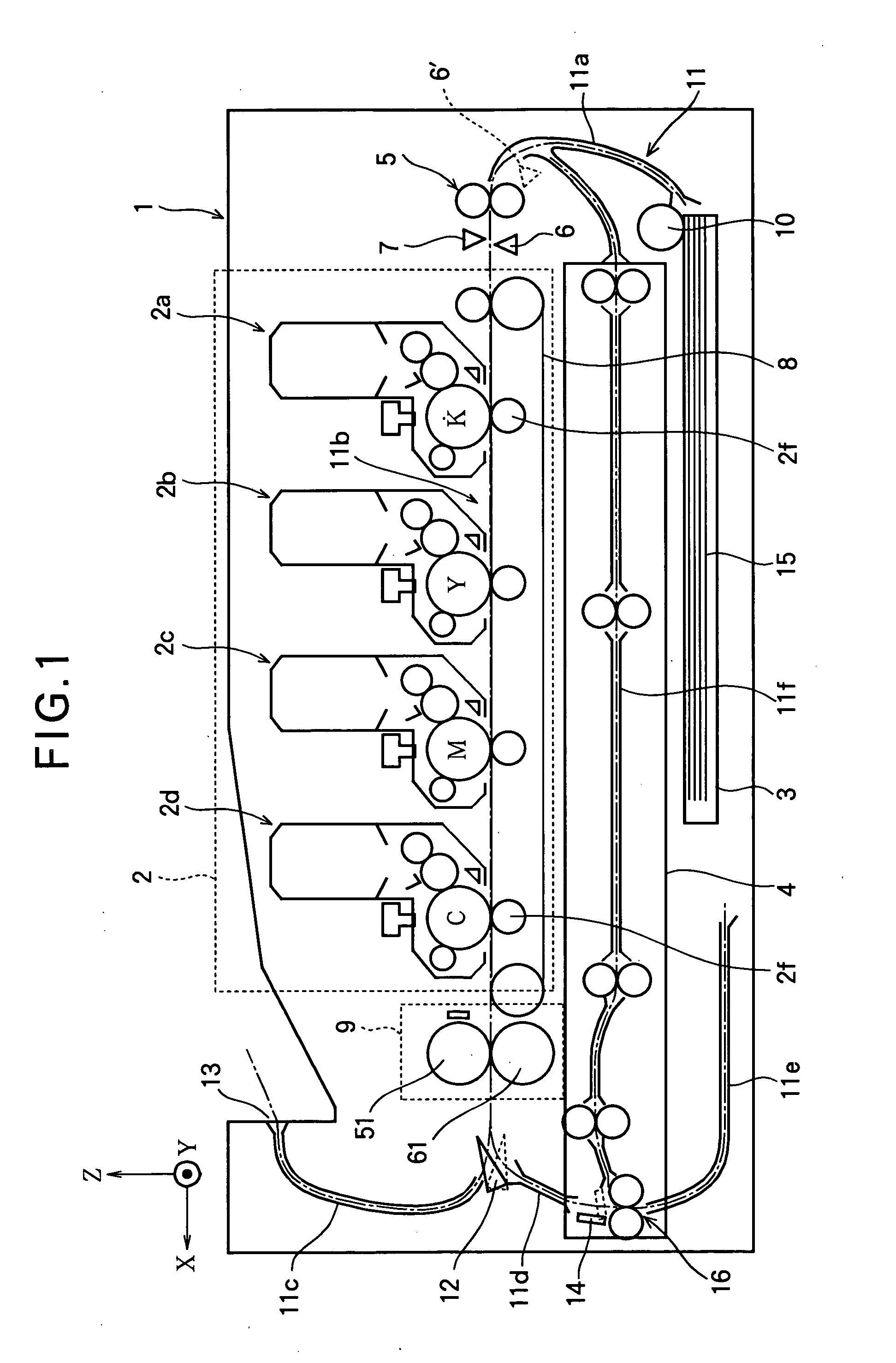
[0029]FIG. 1 is a schematic front view of an image forming apparatus according to Embodiment 1 of the present invention.
[0030] The image forming apparatus 1 includes a cassette mounting portion to which a feeding tray 3 is mounted. In the feeding tray 3, a stack of recording media 15 (for example, recording papers) is accommodated. The image forming apparatus 1 further includes a duplex feeding unit 4 that feeds the recording medium 15 along a feeding path 11 and turns the recording sheet 15 upside down. The image forming apparatus 1 further includes a print process unit 2 that feeds the recording medium 15 along a feeding path 11, and transfers a toner image to the recording medium 15. The image forming apparatus 1 further includes a fixing unit 9 that fixes the toner image to the recording medium 15.
[0031] The uppermost recording medium 15 of the stack accommodated in the feeding tray 3 is picked up by a hopping roller 10 and fed into a feeding path 11a. The leading edge o...
embodiment 2
[0062]
[0063]FIGS. 5A through 5F are timing charts illustrating the operation of the image forming apparatus according to Embodiment 2 of the present invention. With reference to FIGS. 5A through 5F, the operation of the image forming apparatus according to Embodiment 2 will be described.
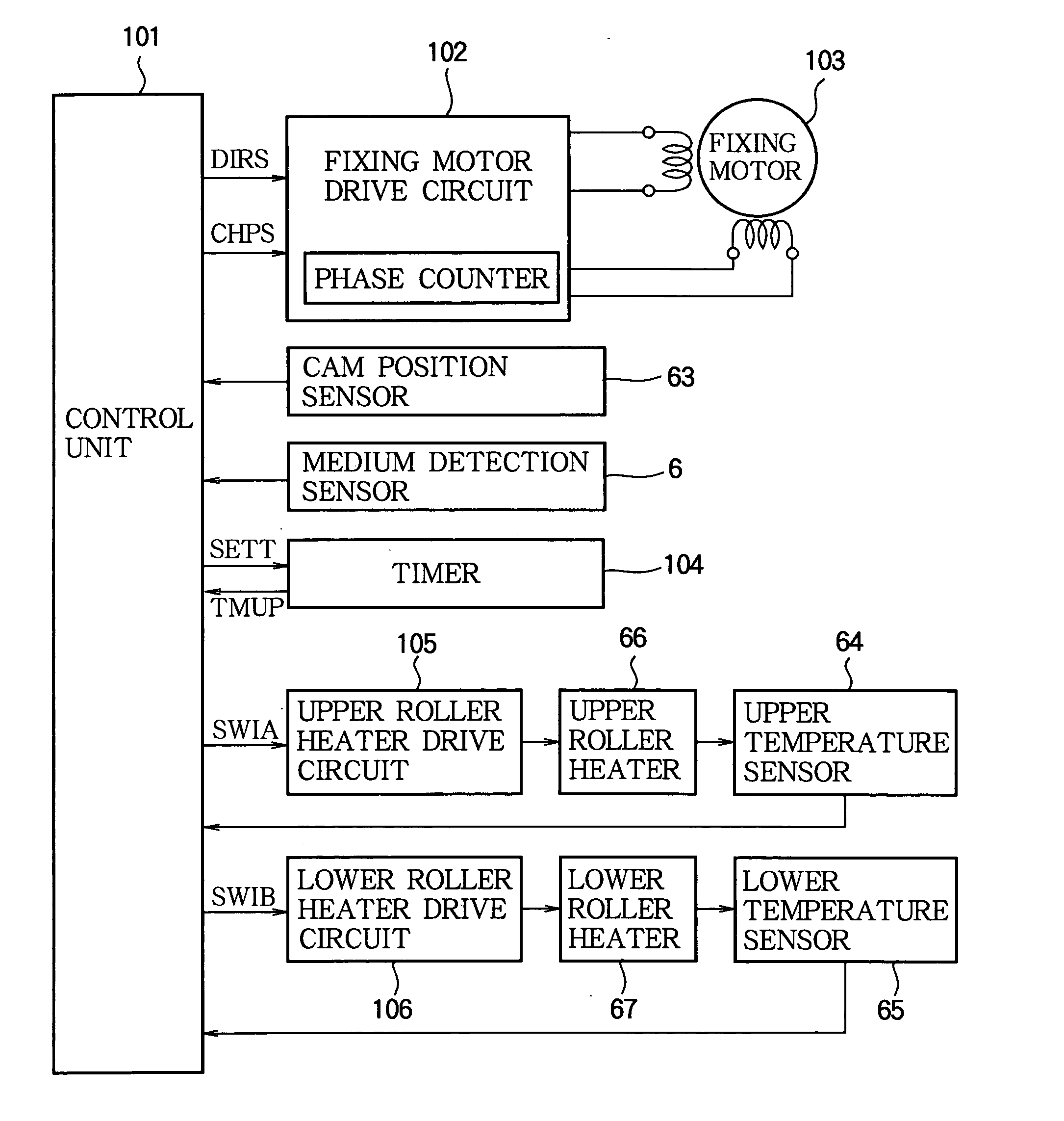
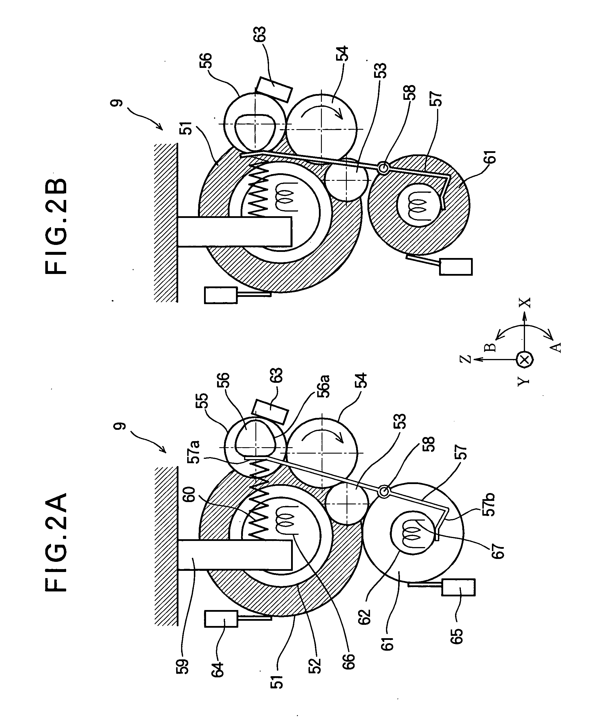
[0064] The structure of the image forming apparatus of Embodiment 2 can be the same as that of the image forming apparatus 1 (FIG. 1) of Embodiment 1. The structure of the control unit 101 of the image forming apparatus of Embodiment 2 is the same as that of the image forming apparatus (FIG. 3) of Embodiment 1. Only a part of the operation of the control unit 101 of Embodiment 2 is different from that of Embodiment 1. Therefore, FIGS. 1 through 3 are referred in the description of Embodiment 2.
[0065] In the printing operation, the processes from time t1 (i.e., when the medium detection sensor 6 detects the leading edge of the recording medium 15) to time t5 (i.e., when the fixing operation is compl...
embodiment 4
[0092]
[0093]FIG. 7 is a block diagram illustrating the control system for controlling the operation of the main part of the image forming apparatus according to Embodiment 4 of the present invention.
[0094] Different from the control system of Embodiment 1, the control system of Embodiment 4 has a block of the thickness sensor 7. Further, a part of the operation of the control system of Embodiment 4 is different from that of Embodiment 1. The components (FIG. 7) in Embodiment 4 that are the same as those described in Embodiment 1 (FIG. 3) are assigned the same reference numbers, and the descriptions thereof are omitted. The structure of the image forming apparatus of Embodiment 4 can be the same as the image forming apparatus 1 of Embodiment 1 (FIG. 1), and therefore the operation will be described with reference to the image forming apparatus 1 as was described in Embodiment 1.
[0095] The thickness sensor 7 shown in FIG. 7 is disposed at the same position as the medium detection se...
PUM
 Abstract
Description
Claims
Application Information
 - R&D
- Intellectual Property
- Life Sciences
- Materials
- Tech Scout
- Unparalleled Data Quality
- Higher Quality Content
- 60% Fewer Hallucinations
Browse by: Latest US Patents, China's latest patents, Technical Efficacy Thesaurus, Application Domain, Technology Topic, Popular Technical Reports.
© 2025 PatSnap. All rights reserved.Legal|Privacy policy|Modern Slavery Act Transparency Statement|Sitemap|About US| Contact US: help@patsnap.com


