Apparatus and associated methods for precision ranging measurements in a wireless communication environment

a technology of wireless communication environment and apparatus, applied in direction finders using radio waves, instruments, reradiation, etc., can solve problems such as the potential of not being realized

Inactive Publication Date: 2005-02-03
INTEL CORP
View PDF3 Cites 133 Cited by
  • Summary
  • Abstract
  • Description
  • Claims
  • Application Information

AI Technical Summary

Problems solved by technology

To date, this potential is yet to be realized, as there is not yet a commercially available UWB solution for this unlicensed application.

Method used


Image

  • Apparatus and associated methods for precision ranging measurements in a wireless communication environment
  • Apparatus and associated methods for precision ranging measurements in a wireless communication environment
  • Apparatus and associated methods for precision ranging measurements in a wireless communication environment

Examples


example operation

Ranging Measurement

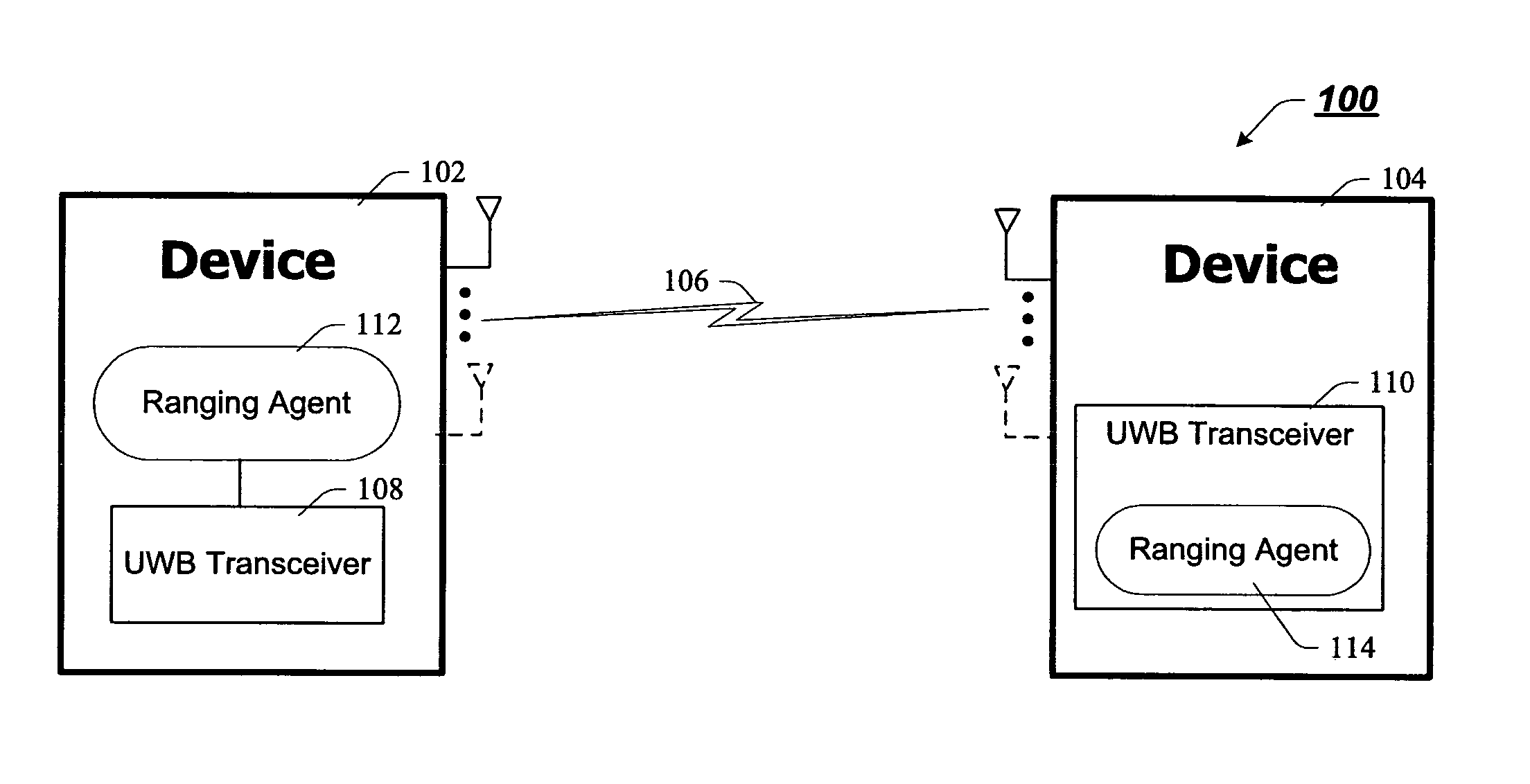
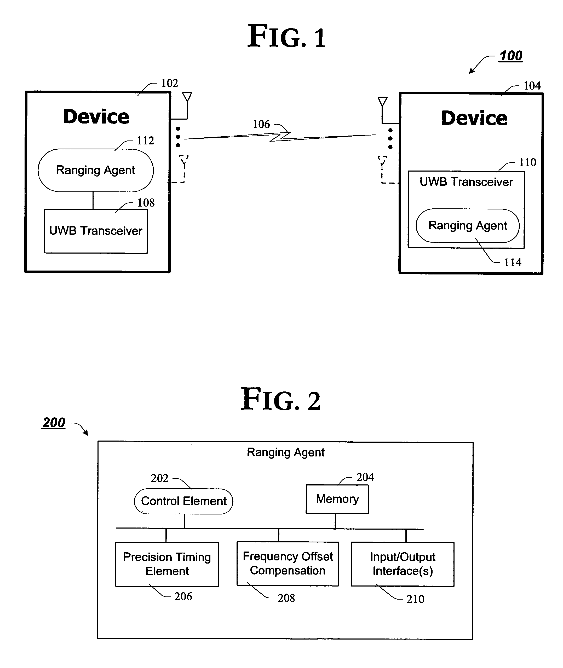
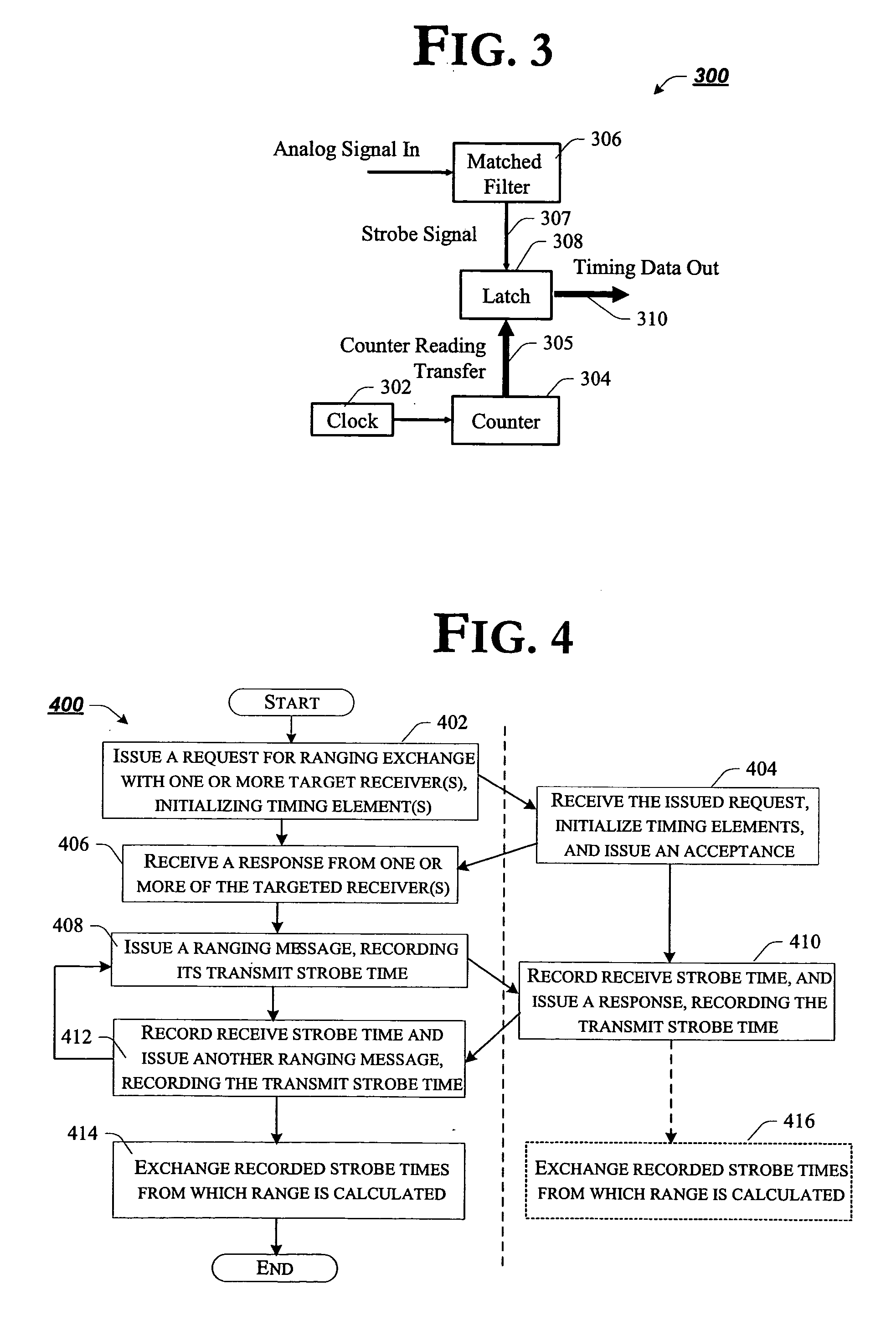
Having introduced an example embodiment of the architecture and operating environment of the ranging agent 200, above, attention is now directed to FIG. 4, where a flow chart of an example method for performing precision ranging measurements in an UWB communication environment is presented, in accordance with but one example embodiment of the invention. For ease of illustration, and not limitation, the method of FIG. 4 is developed with continued reference to FIGS. 1 through 3, as appropriate. Nonetheless, it is to be appreciated that the teachings of FIG. 4 may well be implemented in alternate architectures / environments without deviating from the spirit and scope of the present invention.

FIG. 4 is a flow chart of an example method for precision ranging measurements in an UWB communication environment, according to one example embodiment of the invention. In accordance with the illustrated example embodiment of FIG. 4, the method begins with block 402, wherein...


PUM


Abstract

An apparatus and associated methods to provide precision ranging measurements in an ultrawideband (UWB) wireless communication system are generally described. In this regard, according to one example embodiment, an innovative ranging agent is introduced that effectively computes one or more of the time of signal propagation, the difference in local clocks and frequency offsets to calculate an increasingly accurate estimate of the proximal distance between two or more devices in UWB communication.

Description

TECHNICAL FIELD Embodiments of the present invention are generally directed to wireless communication technology and, more particularly, to an apparatus and associated methods for precision ranging measurements in a wireless communication environment. BACKGROUND Ultrawideband (UWB) wireless communication, in its most basic form, has been around since the beginning of wireless communication. According to one commonly held definition, a UWB signal is any signal wherein the bandwidth divided by the center frequency is roughly 0.25, or more. Recently (Feb. 14, 2002), the United States Federal Communication Commission (FCC) approved the use of a pulsed-RF UWB technology for unlicensed operation. UWB offers the potential to communicate at very high data rates (hundreds of megabits per second) with very low radiated power (200 microwatts or less) over short distances (10 meters or less). To date, this potential is yet to be realized, as there is not yet a commercially available UWB solut...

Claims


Application Information

Patent Timeline
Patent Type & Authority Applications(United States)
IPC IPC(8): G01S19/35G01S5/02G01S13/02H04B1/69
CPCG01S5/021H04B1/7163G01S13/0209G01S5/14
Inventor LEEPER, DAVID G.ENGLAND, DAVID G.HOFFMAN, JEFFREY D.
Owner INTEL CORP
Why Eureka
Try Eureka