Interface unit, lithographic projection apparatus comprising such an interface unit and a device manufacturing method

a technology of interface unit and lithographic projection apparatus, which is applied in the direction of electrical apparatus, printers, instruments, etc., can solve the problems of deterioration of pattern sharpness, time-consuming, and thickness of pattern projection, so as to improve the quality of substrates produced, increase throughput, and improve the effect of quality

Inactive Publication Date: 2005-02-10
ASML NETHERLANDS BV
View PDF12 Cites 183 Cited by
  • Summary
  • Abstract
  • Description
  • Claims
  • Application Information

AI Technical Summary

Benefits of technology

[0016] According to an embodiment of the invention, an interface unit is configured to reduce the possibility of a stand still of the lithographic system. An interface unit for transferring objects such as substrates includes, in an embodiment of the invention, a first object transfer path for transferring objects between a track for processing objects and a lithographic exposure unit for exposing objects, wherein the interface unit is also provided with a second object transfer path extending through a closable transfer opening to an external space for transferring objects between the external space and the lithographic exposure unit. In an embodiment of the invention, the first object transfer path and the second object transfer path are connected. Then, objects can be fed from the external space (outside world), via the respective second object transfer path and the first object transfer path, into the lithographic exposure unit, such that the system can continue operation even in case of a mal-functioning transport system of the track. In this way the track can be bypassed by exchanging objects at the side of the track opposite to the location of the loading / unloading unit.
[0033] According to an embodiment of the invention, the at least one station includes an exchange station configured to exchange substrates towards a space outside the lithographic projection apparatus and the track. The exchange station makes it possible to by-pass the track. Substrates can be delivered and received from the lithographic projection apparatus via the exchange station without using the track. This exchange station is particularly useful in cases where the lithographic projection apparatus is kept at a vacuum and direct exchanging of substrates with the outside world is not possible without providing additional hardware, such as a load lock.

Problems solved by technology

These two different timing principles may yield a timing problem with respect to the exchange of objects between the track and the lithographic apparatus.
The line thickness of the pattern projected in the resist can change between the exposure and the post-exposure bake and also the sharpness of the pattern can deteriorate.
Gasses resulting form the outgassing may disturb the vacuum and may also contaminate the inside of the lithographic projection apparatus.
However, objects (substrates) delivered to the lithographic projection apparatus by a track are often contaminated, which can have a negative effect on the working of the lithographic projection apparatus.
The manufacturer of the lithographic projection apparatus typically has only limited influence on the track used by its customer and such tracks do not always deliver objects (substrates) that fulfill the demands concerning contamination of the lithographic projection apparatus.
Failure to meet these demands could, for example, result in more frequent cleaning operations of the lithographic projection apparatus, which limits the production capacity of the lithographic projection apparatus and reduces the output of good substrates per hour.
This exchange station is particularly useful in cases where the lithographic projection apparatus is kept at a vacuum and direct exchanging of substrates with the outside world is not possible without providing additional hardware, such as a load lock.

Method used


Image

  • Interface unit, lithographic projection apparatus comprising such an interface unit and a device manufacturing method
  • Interface unit, lithographic projection apparatus comprising such an interface unit and a device manufacturing method
  • Interface unit, lithographic projection apparatus comprising such an interface unit and a device manufacturing method

Examples


Embodiment Construction

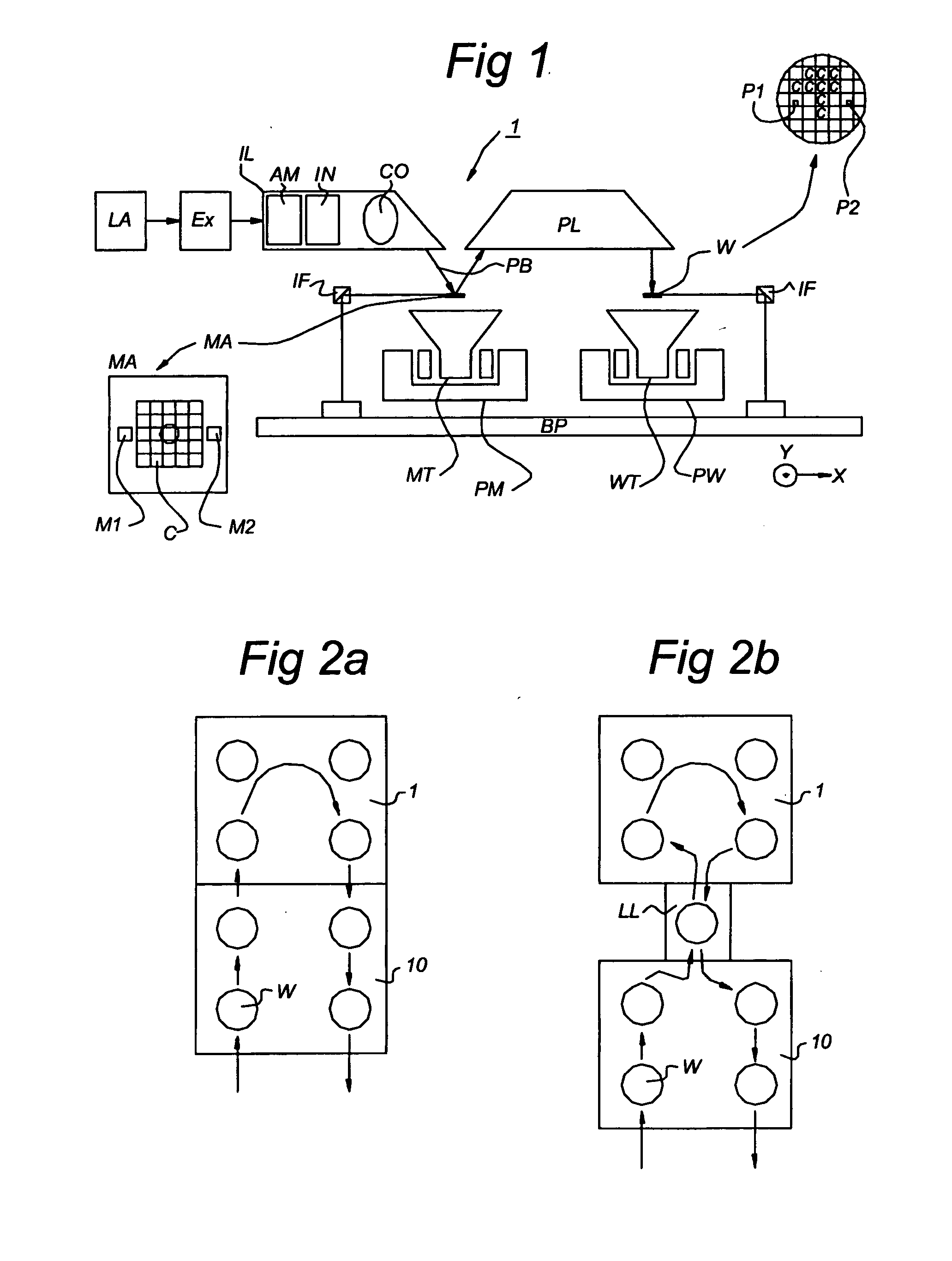
[0052]FIG. 1 schematically depicts a lithographic projection apparatus 1 according to an embodiment of the invention. The apparatus includes a radiation system Ex, IL, configured to supply a beam PB of radiation (e.g. EUV radiation). In this particular case, the radiation system also includes a radiation source LA. The apparatus also includes a first object table (mask table) MT provided with a mask holder configured to hold a mask MA (e.g. a reticle), and connected to a first positioning device PM configured to accurately position the mask with respect to the projection system (“lens”), item PL, The apparatus further includes a second object table (substrate table) WT provided with a substrate holder configured to hold a substrate W (e.g. a resist-coated silicon wafer), and connected to a second positioning device PW configured to accurately position the substrate with respect to the projection system (“lens”), item PL, the projection system (“lens”) PL (e.g. mirrors or lenses) bei...


PUM

PropertyMeasurementUnit
wavelengthaaaaaaaaaa

Abstract

An interface unit for transferring objects, such as substrates, is presented. The interface unit includes a first object transfer path to transfer objects between a track configured to process objects and a lithographic exposure unit configured to expose objects, wherein the interface unit is also provided with a second object transfer path extending through a closable transfer opening to an external space to transfer objects between the external space and the lithographic exposure unit. Furthermore, the invention relates to a lithographic apparatus provided with a lithographic exposure unit and an interface unit according to the invention.

Description

PRIORITY INFORMATION [0001] This application claims priority from European Patent Application No. 03077470.7, filed Aug. 7, 2003, the content of which is herein incorporated by reference in its entirety. BACKGROUND [0002] 1. Field of the Invention [0003] The present invention relates to lithographic apparatus and methods [0004] 2. Description of the Related Art [0005] Lithographic projection apparatus can be used, for example, in the manufacture of integrated circuits (ICs). In such a case, the patterning device may generate a circuit pattern corresponding to an individual layer of the IC, and this pattern can be imaged onto a target portion (e.g. including one or more dies) on a substrate (silicon wafer) that has been coated with a layer of radiation-sensitive material (resist). In general, a single wafer will contain a whole network of adjacent target portions that are successively irradiated via the projection system, one at a time. [0006] In current apparatus, employing patterni...

Claims


Application Information

Patent Timeline
Patent Type & Authority Applications(United States)
IPC IPC(8): H01L21/027G03F7/20
CPCG03F7/7075G03F7/70733
Inventor AUER-JONGEPIER, SUZAN LEONIEMARIUS VAN GROOS, PIETER JOHANNES
Owner ASML NETHERLANDS BV
Why Eureka
Try Eureka