
Method of buffer management in video encoder

Inactive Publication Date: 2005-02-10
LITE ON
View PDF1 Cites 14 Cited by
  • Summary
  • Abstract
  • Description
  • Claims
  • Application Information

AI Technical Summary

Benefits of technology

It is therefore an object of the invention to provide a buffer management method capable of preventing the buffer overflow in a video encoder.

Problems solved by technology

However, if the discarded encoded data is the I picture, the subsequent picture decoding process of the P picture or B picture cannot be performed.

Method used


Image

  • Method of buffer management in video encoder
  • Method of buffer management in video encoder
  • Method of buffer management in video encoder

Examples


Embodiment Construction

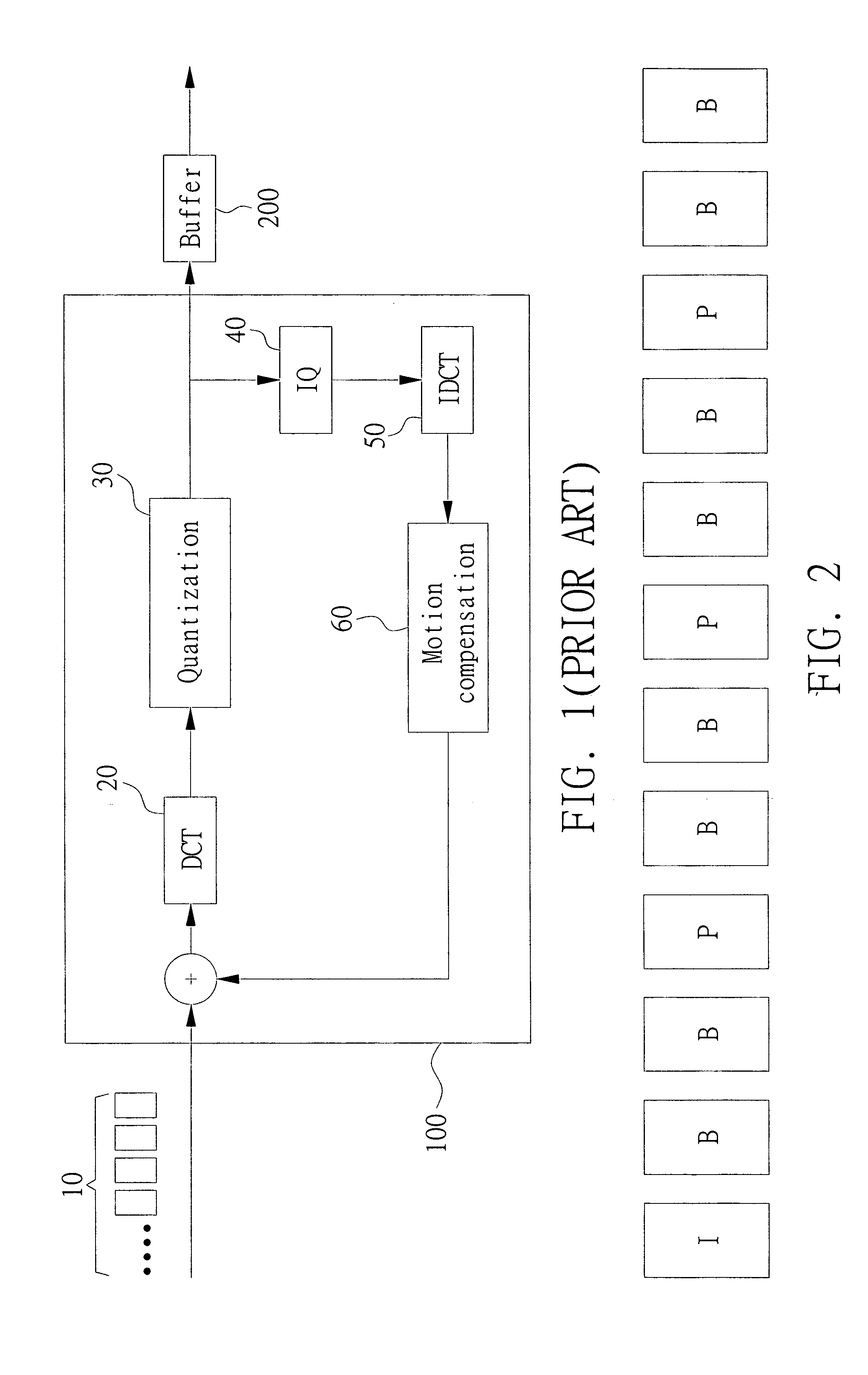
FIG. 2 is a schematic illustration showing a GOP. It is assumed that the data transmission rate (Bit Rate, bits / s) of the buffer is 50 Mbit / s and the frame rate (picture / s) is 30. Thus, the BGOP (Bit In One GOP) of the GOP of 12 pictures in FIG. 2 may be calculated as:

BGOP=12*50M / 30=20M (bits).

That is, the encoded data generated after the picture encoding processes for all of the pictures in the GOP have to be within a predetermined range above or below 20 Mbits.

Furthermore, the encoded data quantities of the I, P and B pictures are not totally the same after the picture encoding processes. In general, the encoded data quantity of the I picture is the greatest, the encoded data quantity of the P picture is the secondary, and the encoded data quantity of the B picture is the smallest. That is, B(I)>B(P)>B(B), wherein B(I) represents the encoded data quantity of one I picture, B(P) represents the encoded data quantity of one P picture, and B(B) represents the encoded data quantity...


PUM


Abstract

A method for buffer management in a video encoder is provided. When a possibility of buffer overflow is higher, a filter function is enabled in an I picture and a not coded function is enabled in a P or B picture. Furthermore, when the fullness of buffer reaches a predetermine threshold, the filter function is enabled in the I picture and a skip function is directly enabled in the P or B picture.

Description

This application claims the benefit of Taiwan application Serial No. 92121920, filed Aug. 8, 2003, the subject matter of which is incorporated herein by reference. BACKGROUND OF THE INVENTION 1. Field of the Invention The invention relates in general to the video encoder, and more particularly to a method for buffer management in a video encoder. 2. Description of the Related Art FIG. 1 is a schematic illustration showing a conventional video encoder. In general, after pictures 10 have been sequentially inputted to a video encoder 100, the video encoder divides these pictures into a plurality of GOPs (Groups Of Picture). The pictures in each GOP is further divided into the I pictures (Intra Pictures), P pictures (Predictive Pictures), or B pictures (Bidirectionally Predictive Pictures). In the picture encoding process of the I pictures, a function of DCT (Discrete Cosine Transfer) 20 and a function of quantization (Q) 30 are enabled. Thereafter, the picture encoding process of t...

Claims


Application Information

Patent Timeline
IPC IPC(8): H04N7/26H04N7/32H04N7/50
CPCH04N19/50H04N19/159H04N19/172H04N19/149H04N19/18H04N19/132H04N19/14H04N19/152H04N19/61
Inventor SHEN, CHIH-CHIANGYEH, MEI-CHEN
Owner LITE ON
Features
  • Generate Ideas
  • Intellectual Property
  • Life Sciences
  • Materials
  • Tech Scout
  • Unparalleled Data Quality
  • Higher Quality Content
  • 60% Fewer Hallucinations
Learn More