Image forming apparatus

a technology of forming apparatus and forming tube, which is applied in the direction of electrographic process apparatus, instruments, optics, etc., can solve the problems of affecting the safety of the developing device removing work, the possibility of generating abnormal rotation for a malfunction of the stepping motor, and the wear and tear of the clutch, so as to prevent the counter-rotation of the developing unit, promote the safety of the operator, and prevent the damage of the developing device or peripheral equipmen

Inactive Publication Date: 2005-02-10
KK TOSHIBA +1
View PDF9 Cites 0 Cited by
  • Summary
  • Abstract
  • Description
  • Claims
  • Application Information

AI Technical Summary

Benefits of technology

[0012] An object of the present invention is to provide an image forming apparatus that is capable of preventing the counter-rotation of a developing unit when exchanging developing devices held by a revolver type developing unit, promoting safety of operator during the maintenance work, and assuring prevention of damage of developing devices or peripheral equipment.

Problems solved by technology

In both methods, it is necessary to prevent a developing unit from rotating in the reverse direction for a malfunction when a developing unit is unbalanced when removing developing devices from a revolver.
Therefore, for example, even when a developing unit is blocked to rotate by a plunger or a one-way clutch, there is still the possibility for generating abnormal rotation for a malfunction of a stepping motor.
Furthermore, the above-mentioned conventional image forming apparatus is in such a structure that a one-way clutch is installed to the central shaft of a developing unit and the one-way clutch is easily worn by the rotation of a developing unit, the clutch accuracy drops for its wear and tear and a certain play may be produced during the operation of the one-way clutch.
Therefore, for example, when the central shaft of the developing unit rotates in conjunction with the rotation of a developer conveying auger of developing devices, a play is produced when the one-way clutch is operating, and when the developing unit rotates in the reverse direction even if only slightly, not only safety in the developing device removing work is impaired but also the developing devices can be damaged.

Method used


Image

  • Image forming apparatus
  • Image forming apparatus
  • Image forming apparatus

Examples


Embodiment Construction

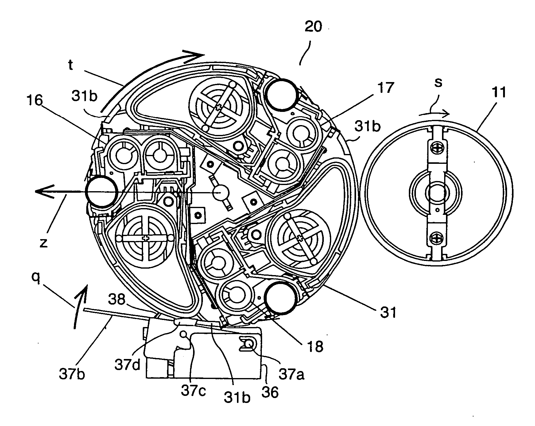
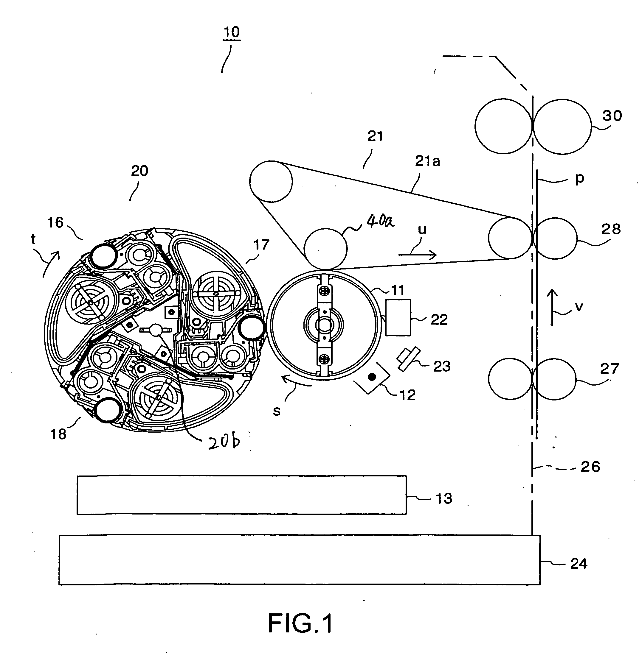
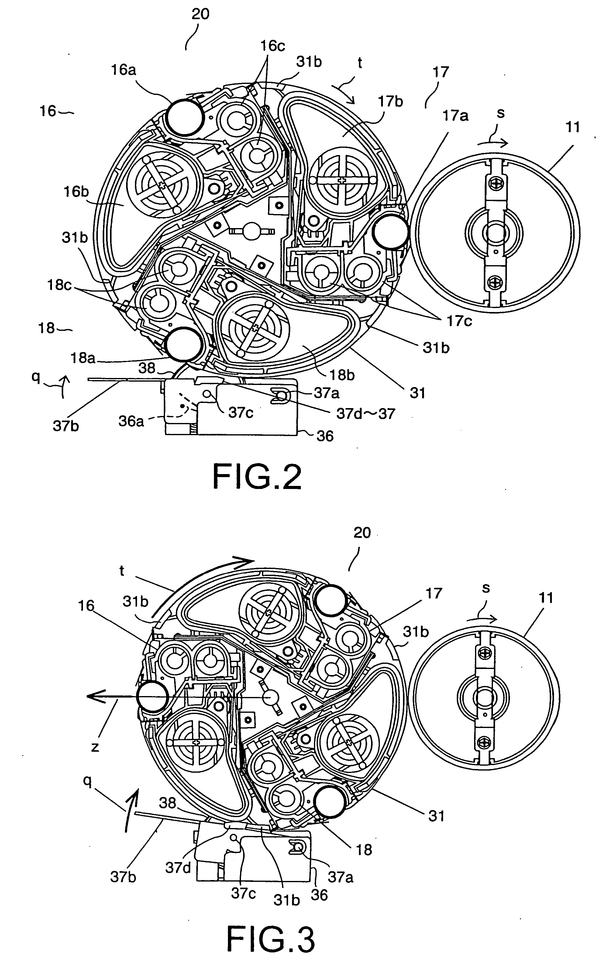
[0023] A preferred embodiment of the present invention will be explained in detail referring to the attached drawings. FIG. 1 is a schematic diagram showing the structure of an image forming unit 10 of an image forming apparatus such as a color printer and the like in the embodiment of the present invention. Around a photosensitive drum 11 that is an image carrier of the image forming unit 10, there are provided a charger 12 to uniformly charge the photosensitive drum 11 sequentially with the rotation of the photosensitive drum 11 in the arrow direction s, a laser writing unit 13 that is a latent image forming unit for forming latent images on the charged photosensitive drum 11, first through third developing devices 16-18 containing three color toners; yellow (Y), magenta (M) and cyan (C), a revolver type developing unit 20 that rotates in the arrow direction t centering around a shaft 20b, an intermediate transfer device 21 equipped with an intermediate transfer belt 21a that rota...


PUM


Abstract

An image forming apparatus includes a main body, an image carrier provided in the main body and configured to retain electrostatic latent images on its surface, and a developing unit including a holding unit holding plural developing devices, rotatably supported by the main body. Further, a driving source is configured to rotate the developing unit and move a desired developing device to a developing position opposed to the image carrier. A stopping member is configured to be moved to an unstopping position unengaged with the holding unit and to a stopping position to stop a one-way direction rotation of the developing unit at an exchanging position for exchanging the developing devices. A backstop member is configured to be moved to a removing position unengaged with the holding unit and to an engaged position engaged with the holding unit to prevent a rotation of the developing unit in a direction opposite the one-way direction rotation.

Description

[0001] The present application is a continuation of U.S. application Ser. No. 10 / 301,798, filed Nov. 22, 2002, the entire contents of which are incorporated herein by reference.BACKGROUND OF THE INVENTION [0002] 1. Field of the Invention [0003] The present invention relates to image forming apparatuses such as electro-photographic apparatuses, printers and the like, and an image forming apparatus to get color developed images using a revolver type developing unit. [0004] 2. Description of the Related Art [0005] In image forming apparatuses to get color images according to an electro-photographic system such as color copiers, printers and the like, for achieving the downsizing, an apparatus is developed, which forms latent images corresponding to yellow (Y), magenta (M), cyan (C) and black (BK) on a photosensitive drum by rotating the drum plural times and supplies toners in different colors to the drum from plural developing devices visualizes the formed color images and obtains a f...

Claims


Application Information

Patent Timeline
Patent Type & Authority Applications(United States)
IPC IPC(8): G03G21/00G03G15/01G03G15/08
CPCG03G15/0121G03G2215/0177G03G2215/0116
Inventor GUMBE, EIJI
Owner KK TOSHIBA
Why Eureka
Try Eureka