Adjustable dental impression tray

a tray and adjustment technology, applied in the field of dental impression trays, can solve the problems of not being able to adjust the tray to the width, the inability to adjust the width of the tray, so as to save time, reduce the large inventory of trays, and improve the accuracy of models

Inactive Publication Date: 2005-02-10
WHITE DENNIS J
View PDF3 Cites 5 Cited by
  • Summary
  • Abstract
  • Description
  • Claims
  • Application Information

AI Technical Summary

Benefits of technology

[0011] Posterior segments of the dental arch often flare toward the buccal especially on the maxilla. This posterior spreading of the upper arch requires wider trays.
[0012] Dentists have many different size and style trays to accommodate different impression challenges. The most significant challenge is meeting the demand for sizing of the dental tray to the different size arches.
[0013] The goal of this disclosure is to reduce the large inventory of trays, save time, and yield more accurate models. One tray will fit many size maxillary and mandibular arches.
[0014] The disclosed tray is readily adjusted. This refinement is made without clamping or screwing.
[0015] Use of this invented tray reduces a large inventory of trays since it is adjustable to fit most applications.
[0016] It is also important to note that most different size trays commercially now available are proportionately larger throughout the entire tray. It clinical use the variable between different arch forms is in the posterior area and not significantly so in the canine to canine anterior areas. This disclosed tray opens wider in these posterior areas.

Problems solved by technology

It can't adjust for different arch widths.
This tray is not adjustable to width.
The most significant challenge is meeting the demand for sizing of the dental tray to the different size arches.
This new tray saves time.
In present art, distortion does happen occasionally at time of tray removal from mouth.

Method used


Image

  • Adjustable dental impression tray
  • Adjustable dental impression tray

Examples


Embodiment Construction

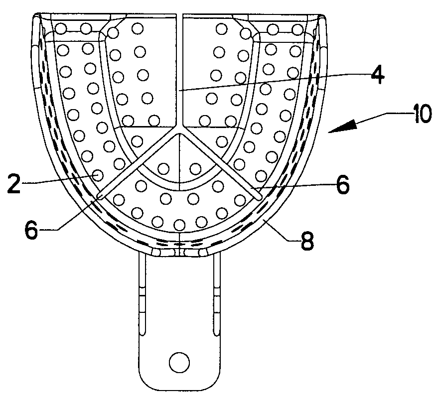
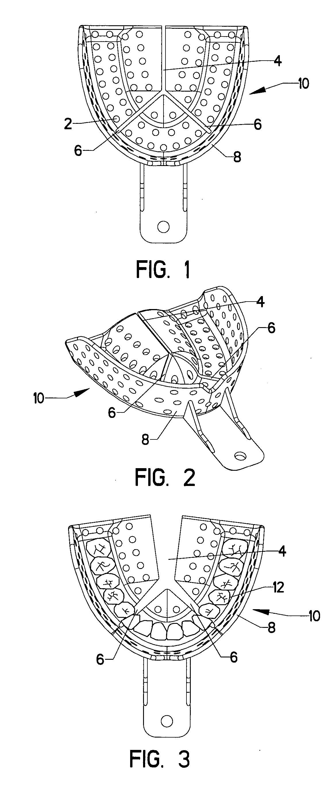
[0023]FIG. 1 shows the maxillary impression tray, 10. The shape overall of the outer wall, 8 is generally horseshoe shaped. There is a longitudinal break, 4, in the palatal aspect or inner wall of tray. There are also oblique breaks, 6, in the anterior palatal portion or connecting base of adjustable tray. The tray has a vertical wall, 8 about the outside periphery. The breaks, 4 and 6 in the tray, 10 do not continue through the vertical wall, 8. This outer vertical wall, 8 supports the segmented areas of the tray, 10. Overall the tray is U shaped to cup over the teeth. Holes, 2 enhance adhesion of impression material to tray, 10.

[0024] In use, the adjustable dental tray, 10, is tried in mouth over teeth, 12, to evaluate the fit of tray, FIG. 3. The tray, 10 is removed from the mouth. It is then simply sprung open manually to assume a wider posterior dimension. The fit of tray, 10, FIG. 3, is verified in the mouth over the teeth, 12. It may again be readjusted. The final tray adjus...


PUM


Abstract

This invention discloses a new dental impression tray that is adjustable without a clamping means. The single sized tray serves for all the different arch size configurations. Most tray fitting problems arise in adaptation in the posterior segment. This tray is simply spread apart to adapt to size of arch and used directly with no clamping or fixation. The newly adjusted tray's shape is maintained by only the integrity of the outer wall.

Description

FIELD OF INVENTION [0001] This invention relates to dental impression trays. Dental impression trays are used to support impression material which is utilized by dental care providers to capture an imprint of the dental form. DESCRIPTION OF THE PRIOR ART [0002] Dental impression trays are used to bring curable impression compounds into the oral cavity. Also, when timing dictates, this tray serves to remove this set material from the mouth. It also serves to support the resultant impression mold while mixed stone or other hardening materials are utilized. This formed cast of the mouth may then be used for study. [0003] The many different sizes and shapes of the dental arch necessitate many different sizes of trays. [0004] This application discloses a tray that can be adjusted in the posterior segment. This adjustment can allow for wider mouths. It can therefore accommodate many arch configuaraions and reduce the number of trays needed for inventory. [0005] In U.S. Pat. No. 1,499,482,...

Claims


Application Information

Patent Timeline
Patent Type & Authority Applications(United States)
IPC IPC(8): A61C9/00
CPCA61C9/0006
Inventor WHITE, DENNIS J.
Owner WHITE DENNIS J
Why Eureka
Try Eureka