Golf club, jetdrv driver for increased distance and accuracy

a technology of golf club and driver, which is applied in the field of golf club and jetdrv driver for increasing distance and accuracy, can solve the problems of uncontrollable slice, unfavorable claim, and inability to swing the same club at the higher speed without introducing an uncontrollable slice, so as to improve strike accuracy, improve strike accuracy, and reduce clubhead mass and aerodynamic drag

Inactive Publication Date: 2005-02-10
VAN NIMWEGEN ROBERT ROY
View PDF3 Cites 46 Cited by
  • Summary
  • Abstract
  • Description
  • Claims
  • Application Information

AI Technical Summary

Benefits of technology

[0014] The third most helpful book “The Physics of Golf”, by Theodore P. Jorgensen Department of Physics and Astronomy University of Nebraska. This book provides an excellent quantitave comparison of an analytical treatment of the golf club swing and corrolates these results with experimental measured data. Additionally a computer program is provided in Qbasic by The American Institute of Physics. This program was modified by the inventor to include the effects of the aerodynamic drag on the clubhead and shaft. Results of this analysis were used to study the clubhead-to-ball transfer of energy and how it can be controlled to improve strike accuracy. The ball is assumed to be a spherical spring and the clubhead a ridge anvil to deform the ball in a desirable manner, controlling ball spin and direction. Kinetic energy transferred from clubhead to ball is proportional to the square of the club velocity at impact and directly as the ratio of the mass of the clubhead to the mass of the ball. Clubhead mass and aerodynamic drag is reduced to provide a higher velocity for the same energy input by the golfer. The center of gravity of the clubhead is more closely alligned with the shaft axis to ensure contact alignment between center of gravity of the clubhead and the ball, namely the sweet spot.

Problems solved by technology

Clubhead speeds of 120 miles per hour could result in 260 yard drives, however, if the clubhead is only two degrees off normal when striking the ball, this will cause the drive to be off the aiming point by this angular error of at least nine yards.
It is not practical to swing the same club at the higher speed without introducing an uncontrollable slice.
This claim is impossible since the center of precussion is close to the club center of gravity.
The inventors error is in the selection of the shaft centerline as the pivot point in the analysis rather than at the wrist-cock-axis.

Method used


Image

  • Golf club, jetdrv driver for increased distance and accuracy
  • Golf club, jetdrv driver for increased distance and accuracy
  • Golf club, jetdrv driver for increased distance and accuracy

Examples


Embodiment Construction

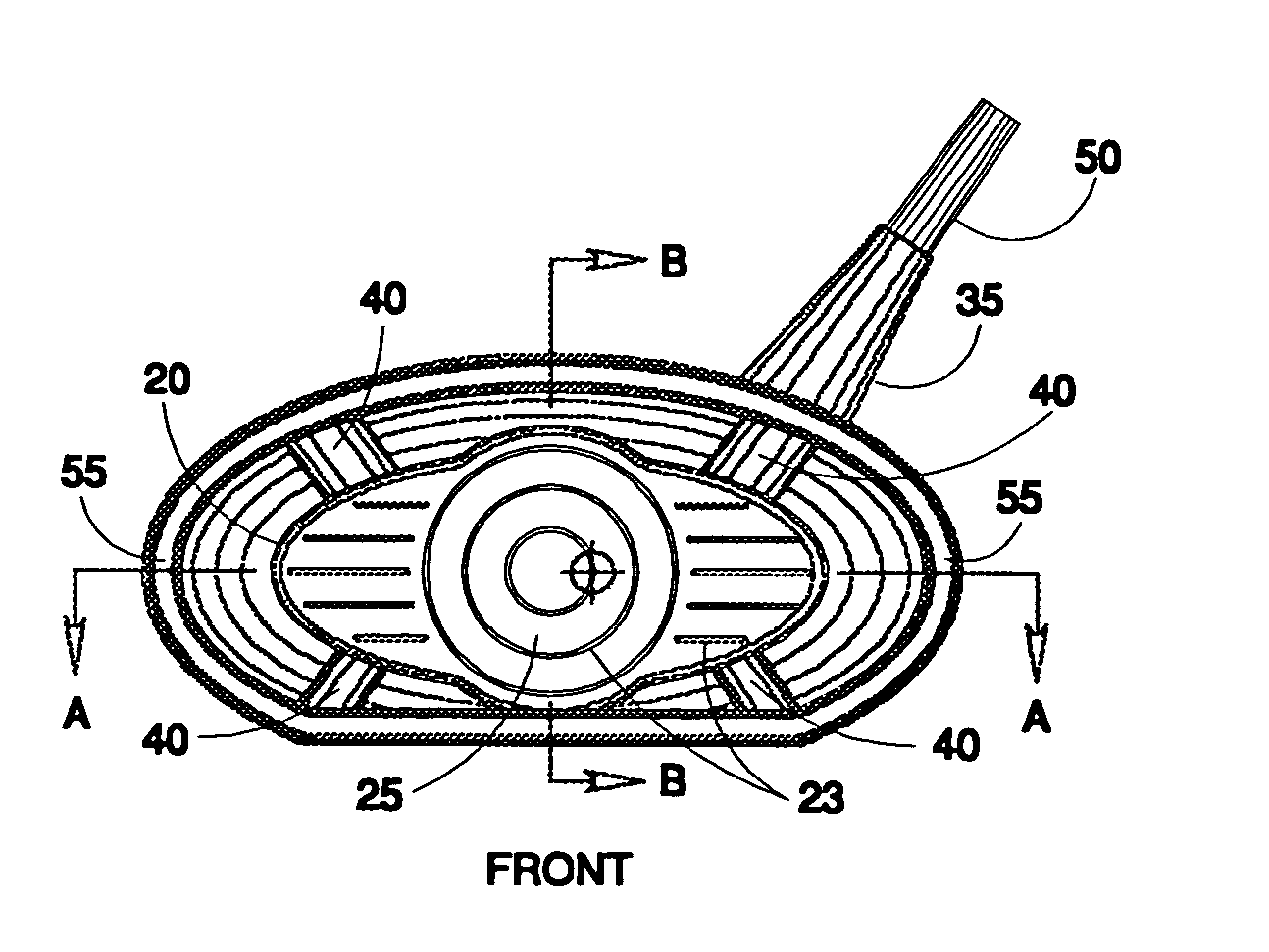
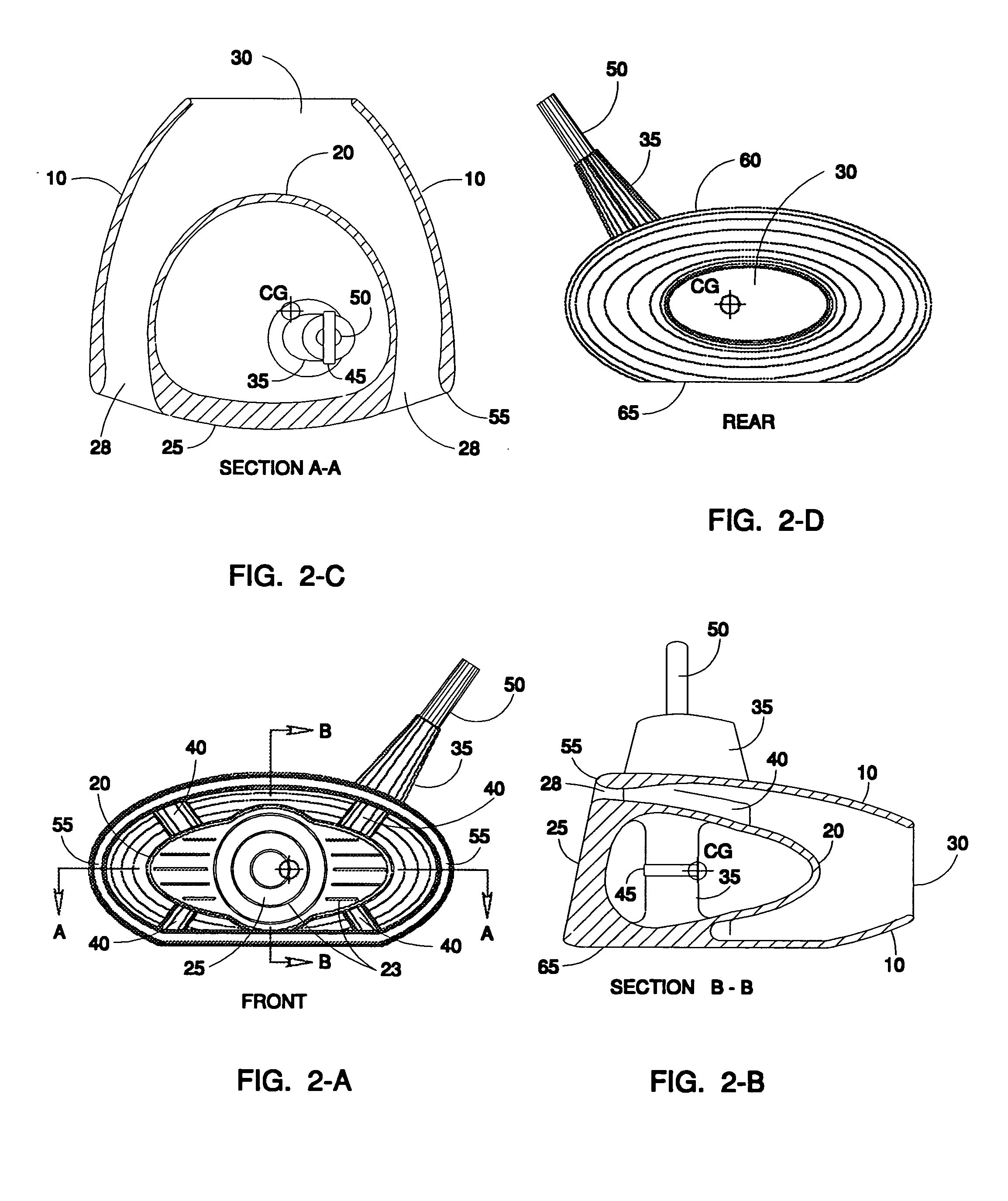
[0023] The embodiments of the golf club proposed is illustrated in FIG. 2A, front view, and FIG. 2D, rear view, with the top view of the cross section FIG. 2C, and cross section of the side view FIG. 2B. The clubhead 20, with the striking face 25 has a plurality of score lines 23. An elliptical shaped nacelle 10, attached to the clubhead by four support struts of airfoil cross section 40. The leading edge of the nacelle has an elliptical cross section 55 for low drag in guiding the air past the nacelle leading edge. The club shaft 50 is attached to the hosel 35, the support strut 40 and the internal cylindrical shroud 35. The shaft 50, can be a hollow steel shaft or solid graphite filament that is bonded to the aluminum clubhead. For safety in reduncy, a roll pin or steel rivit 45 is inserted through the shaft attaching it to the cylindrical shroud 35. Air enters the passage 28 between the nacelle 10 and the clubhead 20 where the flow area change diffuses the flow reducing its veloc...


PUM


Abstract

A golf club, a driver, designed to provide an inprovement in the accuracy of ball control as club head speeds are increased from 100 miles per hour to the level of a semipro at 120 miles per hour. Most forces on the club head increase as the square of the velocity, representing a forty four percent increase. A detailed analysis has been made of forces generated during the collision of the ball and club head and their effect on trajectory of the ball. The design proposed greatly reduces the aerodynamic drag of the clubhead, increases the allowable tolerance to angular misalignment of the club striking face from two degrees to ten degrees and reduces the torque that twists the club head causing an angular misalignment prior to contact with the ball.

Description

U.S. PATENT DOCUMENTS [0001]3,595,577July 1971Hodge3,625,518December 1971Solheim3,941,390March 1976Hussey4,471,961September 1984Masghati5,354,059October 1994Stuff5,366,223November 1994Werner5,511,786April 1996Antonious5,735,754April 1998Antonious5,971,868October 1999Kosmatka5,997,413December 1999Wood6,139,445October 2000Werner6,190,267February 2001Marlowe6,312,534November 2001Grensing6,319,437November 2001Elsner6,371,868April 2002Galloway6,402,636June 2002Chang6,478,692November 2002KosmatkaBACKGROUND OF THE INVENTION [0002] Golf has become a very popular sport for both the amateur and the professional resulting in rapid improvements in courses, hazzards, clubs and balls. The two clubs which account for the most strokes on the score card are the driver and the putter. The driver is responsible for covering the the majority of the yardage on most courses, and consequently is responsible for getting its owner into the most difficult to impossible lies. Recent trend in driver design has...

Claims


Application Information

Patent Timeline
Patent Type & Authority Applications(United States)
IPC IPC(8): A63B53/04
CPCA63B53/0466A63B2225/01A63B59/0088A63B60/50
Inventor VAN NIMWEGEN, ROBERT ROY
Owner VAN NIMWEGEN ROBERT ROY
Why Eureka
Try Eureka