
Back recess balance weight structure for golf club heads

a golf club and weight structure technology, applied in golf clubs, sport apparatus, golf, etc., can solve the problems of affecting the integrity of the striking face, taking a lot of time, and popular recreational activities, and achieve the effect of reducing the weight of the head and simple structur

Inactive Publication Date: 2007-12-20
SHANGHAI PRECISION TECHNOLOGY CORPORATION
View PDF3 Cites 8 Cited by
  • Summary
  • Abstract
  • Description
  • Claims
  • Application Information

AI Technical Summary

Benefits of technology

[0007]The primary object of the present invention is to provide a back recess balance weight structure for golf club heads that has a simpler structure and a reduced head weight and can move the balance weight to a required location to shift the gravity center to an optimal position.
[0010]1. Striking of the ball is more accurate: As the balance weight structure is located on the back side relative to the striking face of the golf club head, and the back recess body has a plurality of cavities formed in the back recess, the weight of the club head is reduced and the balance weight can be moved to a required location to shift the gravity center to an optimal position. Therefore the accuracy of striking the golf ball can be enhanced.
[0011]2. Simpler structure: The balance weight consists of the back recess body and the sealing cap. The gravity center of the head can be shifted rearwards at the optimal position. As a result, the stability balance and directional control of swinging of the golf club can be improved.

Problems solved by technology

In the past Taiwan was an agricultural society and golf was not a popular recreational activity.
It takes a lot of time and the integrity of the striking face could be damaged.
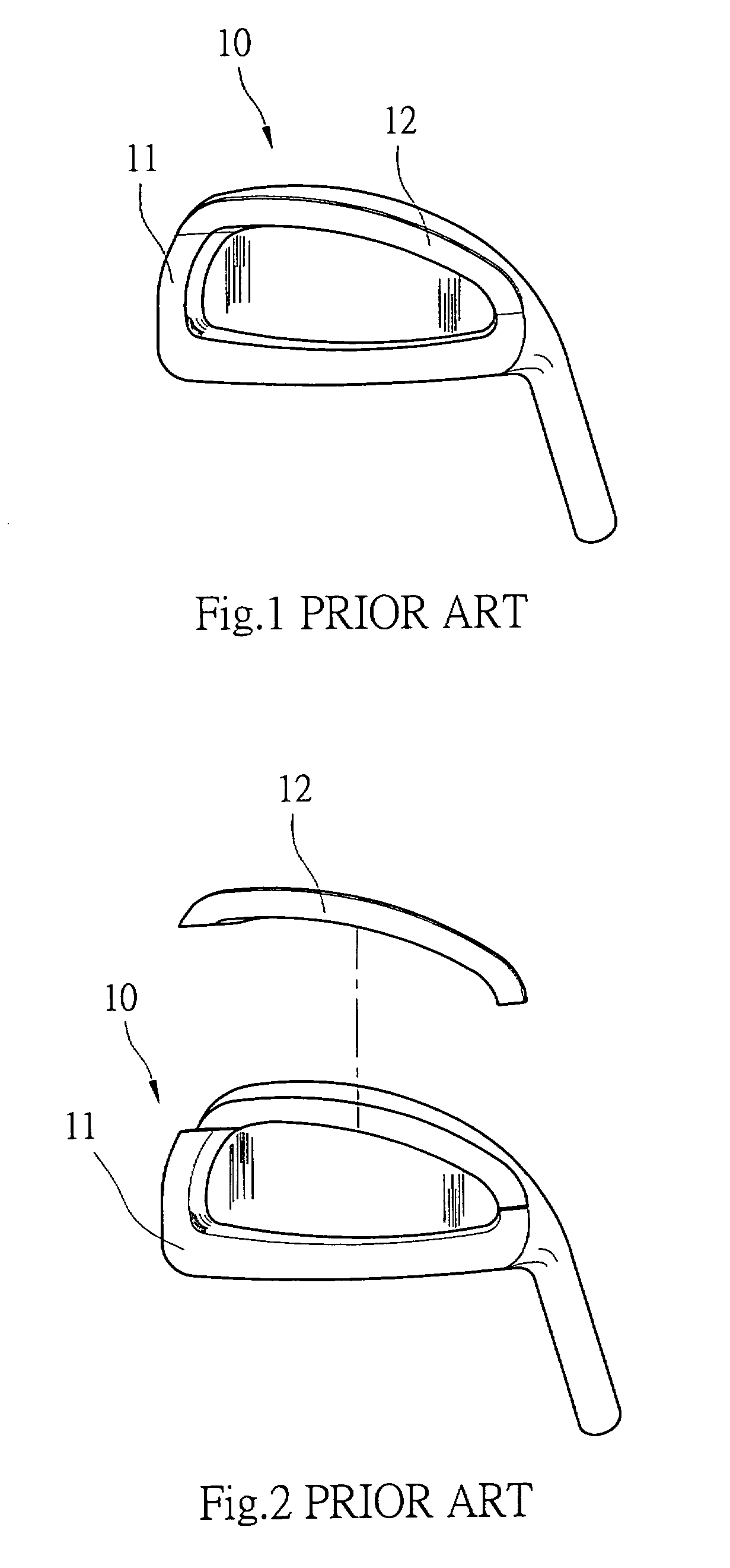
While such an approach can meet user's requirement in some respect, the gravity center still cannot be moved to a desired location to suit the individual user.
Swinging of the club also is not desirable.
And the stability and accuracy of club swinging decrease.
As a result altering of the balance weight structure 12 is not easy, and adjusting the gravity center to the required location is difficult.

Method used


Image

  • Back recess balance weight structure for golf club heads
  • Back recess balance weight structure for golf club heads
  • Back recess balance weight structure for golf club heads

Examples


Embodiment Construction

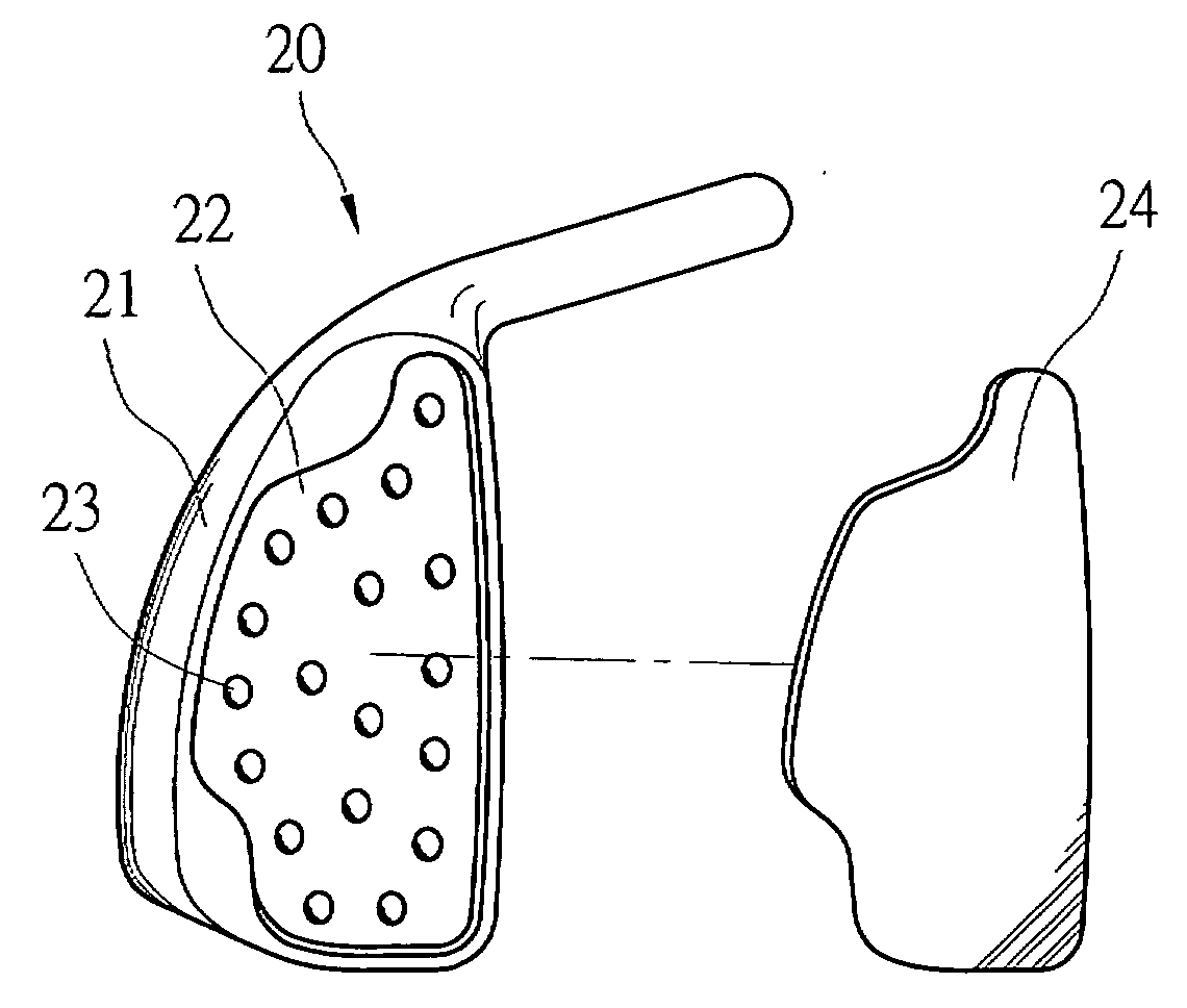
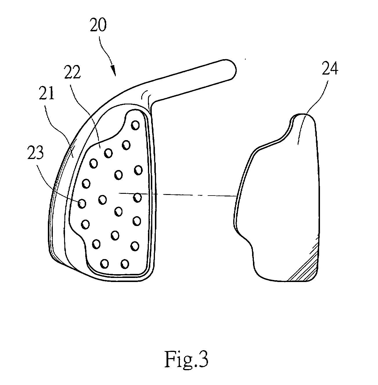
[0019]Please refer to FIGS. 3 and 5, the back recess balance weight structure for golf club heads according to the invention is located on a back side of a golf club head 20 relative to a striking face 25. It includes at least a back recess body 21 and a sealing cap 24.

[0020]Refer to FIGS. 4A and 4B, the back recess body 21 is coupled on a back side of the striking face 25 and has a back recess 22 in which a plurality of cavities 23 are formed to reduce the weight of the golf club head 20.

[0021]The sealing cap 24 is made from material of a smaller specific gravity (such as aluminum, titanium, high strength fiber material or the like). The sealing cap 24 is bonded to the back recess 22 through adhesive to form a tight sealing.

[0022]The back recess 22 in the back recess body 21 can be formed in any profile desired, such as various geometric shapes. An embodiment of an elongate recess is shown in the drawings.

[0023]The sealing cap 24 can also be formed in any profile desired, such as v...


PUM


Abstract

A back recess balance weight structure for golf club heads is located on a back side of a golf club head relative to the striking face and includes a back recess body and a sealing cap. The back recess body has a back recess with a plurality of cavities formed therein. The sealing cap covers the back recess by bonding. The structure consists of simple elements. The sealing cap is made from a material of a smaller specific gravity to move the weight of the club head to the optimal position. The adhesive can absorb shock and vibration to form a tight sealing of the sealing cap and the back recess body. Thereby optimal stability and striking accuracy can be achieved during swinging of the golf club.

Description

FIELD OF THE INVENTION[0001]The present invention relates to a back recess balance weight structure for golf club heads and particularly to a back recess balance weight structure that has a back recess on the back side of the striking face of a golf club head with a plurality of cavities formed thereon and covered by a sealing cap to reduce the weight of the golf club head and move the balance weight to a required location to shift the gravity center to an optimal position to achieve accurate striking of the golf ball.BACKGROUND OF THE INVENTION[0002]Literature records show that golf was invented in England. But in China a game called “Hammering ball” similar to the golf was recorded before the Christian 'era. It is played by hitting a ball with a wooden hammer into a goal. Where the golf was originated is not important now. These days golf is a very popular sport, and even seen as a high-esteemed sport of gentlemen and ladies in many countries.[0003]In the past Taiwan was an agricu...

Claims


Application Information

Patent Timeline
IPC IPC(8): A63B53/00
CPCA63B53/0475A63B2053/0491A63B53/047A63B2053/0416A63B2209/02A63B2209/00A63B53/0416A63B60/02A63B60/54
Inventor LAI, LI-YANGLAI, CHIEN-CHI
Owner SHANGHAI PRECISION TECHNOLOGY CORPORATION
Learn More