Contact lens insertion and removal device

a technology for removing devices and contact lenses, which is applied in the field of instruments and devices for inserting and removing contact lenses, can solve the problems of difficult, if not impossible, to see and locate the lens to be removed, and experience difficulty in inserting and/or removing contact lenses, etc., to prevent excessive suction and the associated risk of damage to the contact lens and/or the eye, and reduce the vacuum

Inactive Publication Date: 2005-02-17
BUTLER JERRY
View PDF8 Cites 3 Cited by
  • Summary
  • Abstract
  • Description
  • Claims
  • Application Information

AI Technical Summary

Benefits of technology

[0006] The present invention provides a device for inserting and removing contact lenses from the eye of a user that overcomes the problems and disadvantages of the prior art. The device of the invention is effective and easy to use, and prevents excessive suction and the associated risk of damage to the contact lens and / or to the eye by limiting the vacuum that can be created by the device.

Problems solved by technology

Since the advent of contact lenses users of the lenses have experienced difficulty inserting and / or removing the lenses.
Typically, the tip of a finger is used to insert the lenses and assist in removing them, but that procedure often has disadvantages.
Removal of contact lenses can be particularly problematic, because the placement of a finger near the eye to remove or to catch a lens obscures visibility with the other eye and makes it difficult, if not impossible, to see and locate the lens to be removed.
Various approaches to solving these problems have been tried, but none have proven to be fully successful.
Some approaches known in the prior art are based upon the use of fairly complex devices that include components for, for example, holding open the eyelids as well as components for holding and inserting a contact lens.
These devices are subject to breakage and are often too bulky for a contact lens wearer to easily carry along for use when the need to remove or insert a lens may arise.
With some devices of this type it is difficult to release the vacuum to release the lens once it is in place on the eye.
With other devices of this general type it is difficult to control the suction, and an excessive suction may be imposed, damaging the lens.
One device known in the prior art attempts to address that problem by providing a barrier to prevent sucking the lens into the suction tube of the device, but does not address the problem of excessive suction directly.

Method used


Image

  • Contact lens insertion and removal device
  • Contact lens insertion and removal device
  • Contact lens insertion and removal device

Examples


Embodiment Construction

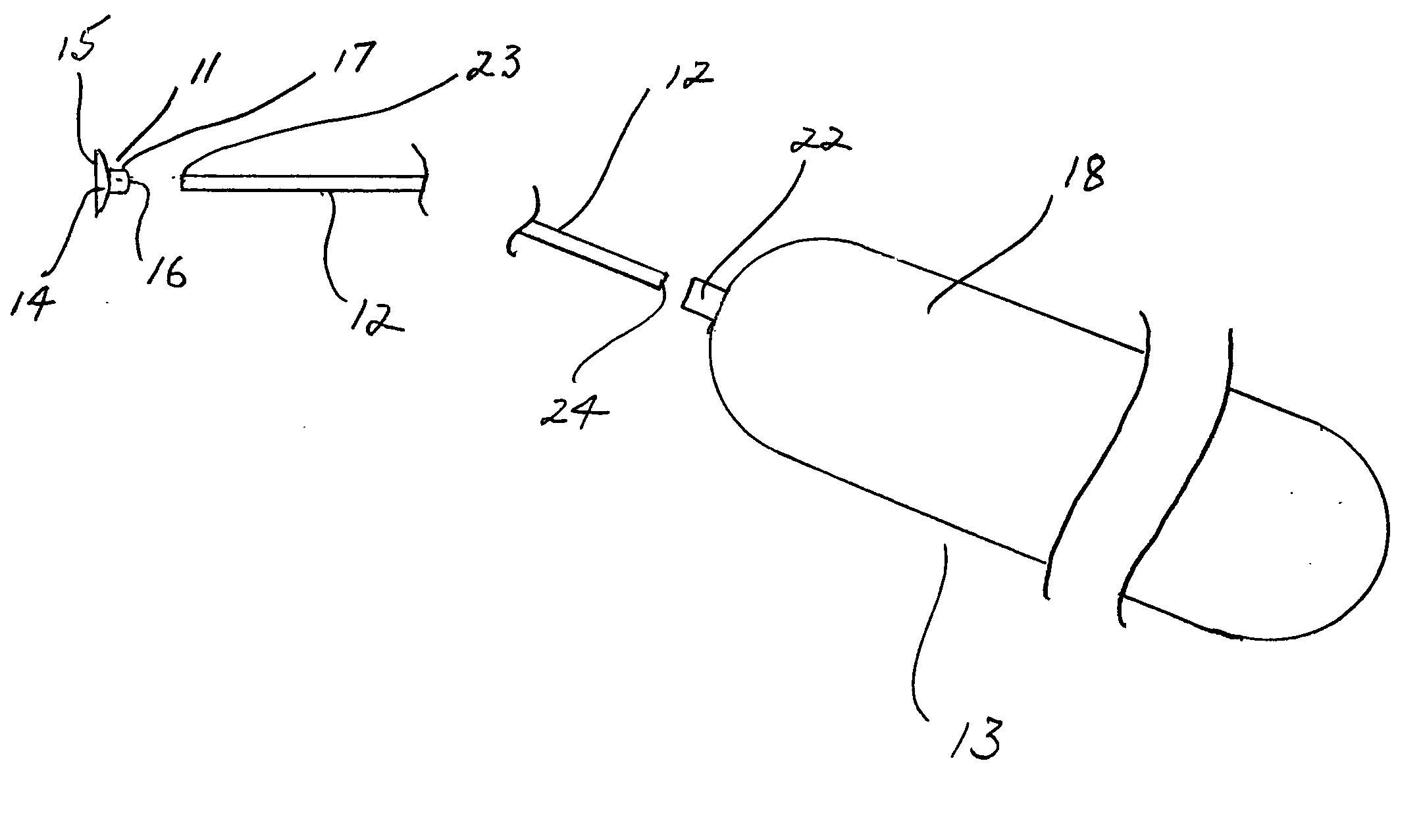
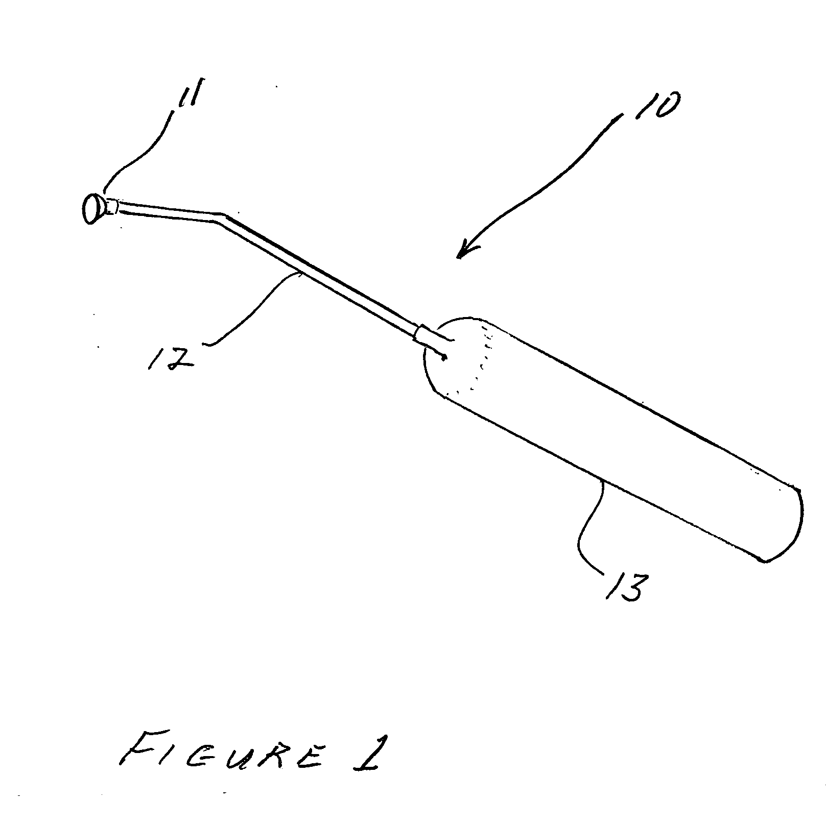
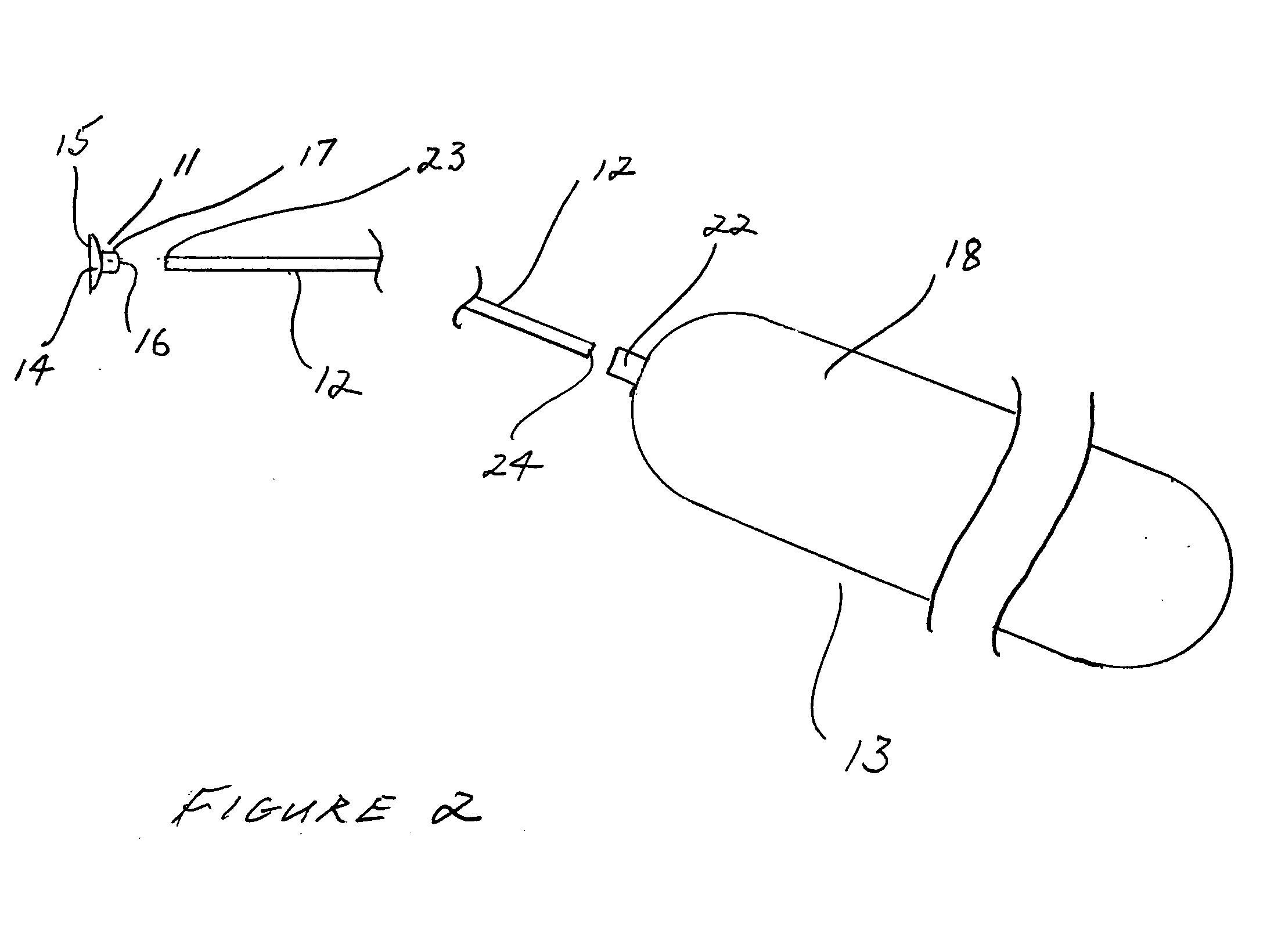
[0015] Referring to the drawing figures, the device of the invention, generally designated by reference numeral 10, comprises the primary components of a lens cup 11, an elongate wand 12, and a handle 13.

[0016] Lens cup 11 is shaped as a suction cup, with a thin, flexible wall 14 of a non-abrasive material, formed in a curved configuration with a radius of curvature slightly less than the typical radius of curvature of a contact lens. In the preferred embodiment the lens cup is configured as a section of the wall of a hollow sphere. Wall 14 thus surrounds an open concave interior, and has a circular outer edge 15. The diameter of the lens cup at the outer edge is preferably significantly less than the diameter of a typical contact lens. Wall 14 is penetrated by a suction aperture 16 that is preferably centered in wall 14, with its axis perpendicular to the plane defined by edge 15. Suction aperture 16 is surrounded by an annular lens cup collar 17. The lens cup is preferably constr...


PUM


Abstract

A contact lens insertion and removal device includes a lens cup with a concave curvature for engaging a contact lens and a central aperture, a deformable shape retentive handle with a limited interior volume from which air can be exchanged between the interior and exterior of the handle, and an elongate hollow wand connected between the handle and the lens cup to form a passageway from the interior of the handle through the central aperture of the lens cup. A contact lens may be engaged with limited suction by the lens cup and released from the lens cup by manipulation of the handle without risk of damage to the contact lens.

Description

RELATED APPLICATION DATA [0001] This application claims the benefits of U.S. Provisional Patent Application Ser. No. 60 / 494,171, filed Aug. 8, 2003, titled “Contact Lens Insertion And Removal Device”.FIELD OF THE INVENTION [0002] The present invention generally relates to the field of instruments for handling contact lenses, and in its preferred embodiments more specifically relates to an instrument or device for inserting and removing contact lenses, including soft contact lenses, from the eye. BACKGROUND [0003] Since the advent of contact lenses users of the lenses have experienced difficulty inserting and / or removing the lenses. Typically, the tip of a finger is used to insert the lenses and assist in removing them, but that procedure often has disadvantages. Removal of contact lenses can be particularly problematic, because the placement of a finger near the eye to remove or to catch a lens obscures visibility with the other eye and makes it difficult, if not impossible, to see ...

Claims


Application Information

Patent Timeline
Patent Type & Authority Applications(United States)
IPC IPC(8): A61F9/00
CPCA61F9/0061
Inventor BUTLER, JERRY
Owner BUTLER JERRY
Why Eureka
Try Eureka