Securement of head rest support into automobile seat frame

a technology for securing head rests and seat frames, which is applied in vehicle safety belts, seating furniture, operating chairs, etc., can solve the problems of unsuitable locking techniques, and achieve the effect of high conventional costs for ensuring security

Inactive Publication Date: 2005-02-17
BEND ALL AUTOMOTIVE
View PDF7 Cites 18 Cited by
  • Summary
  • Abstract
  • Description
  • Claims
  • Application Information

AI Technical Summary

Benefits of technology

[0011] Support tubes for headrests are conventionally attached to the seat frame piece by welding a bracket onto the frame piece, and then welding the tube to the bracket. Sometimes, the tube is pressed into holes in the welded-o

Problems solved by technology

It is recognised that the lock-beading t

Method used


Image

  • Securement of head rest support into automobile seat frame
  • Securement of head rest support into automobile seat frame
  • Securement of head rest support into automobile seat frame

Examples


Embodiment Construction

[0017] By way of further explanation of the invention, exemplary embodiments of the invention will now be described with reference to the accompanying drawings, in which:

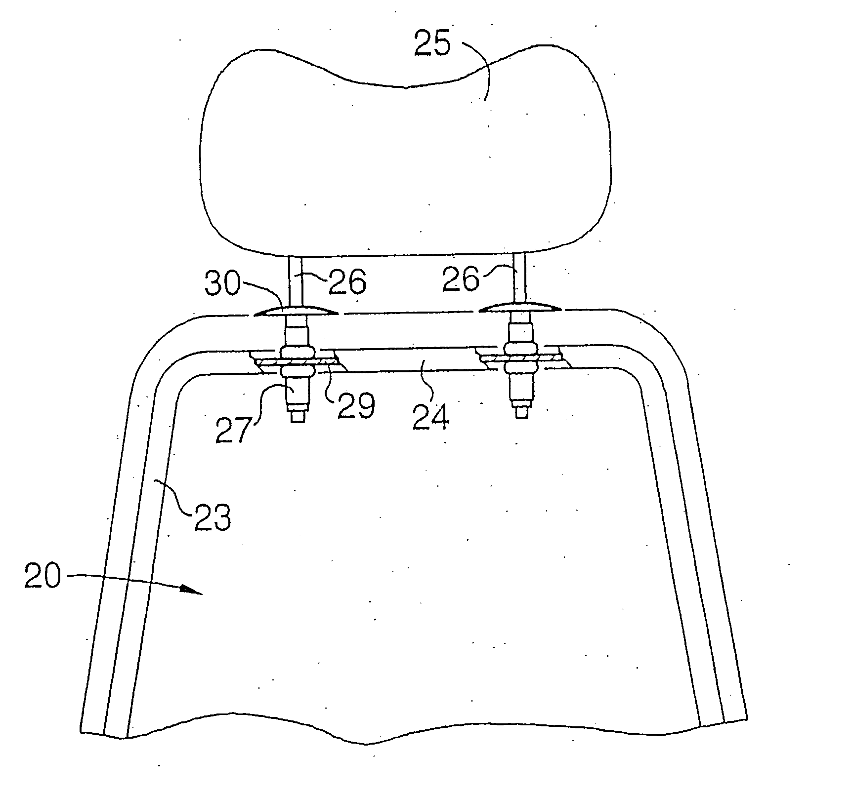
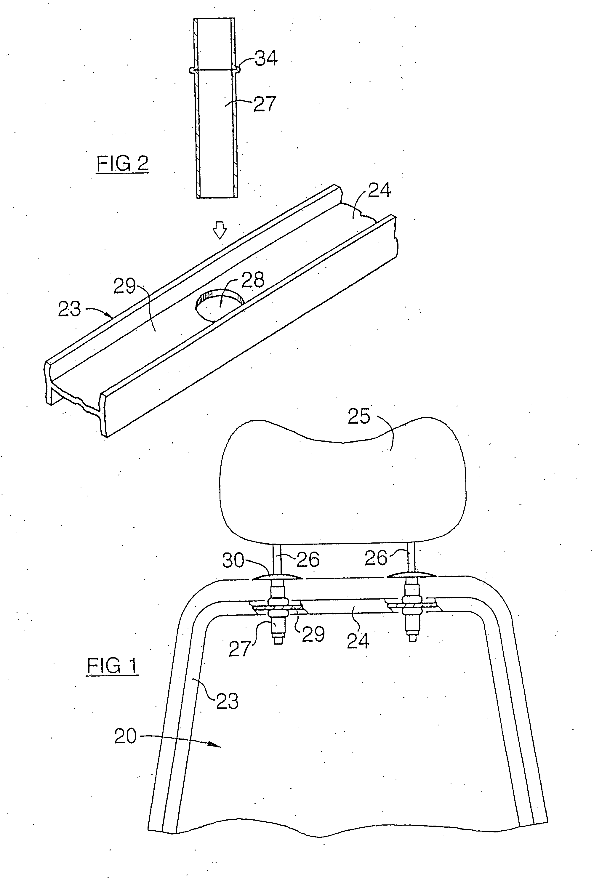
[0018]FIG. 1 is a diagram of an automobile seat frame, shown partly in cross-section, carrying a headrest which is mounted in a manner in accordance with the invention;

[0019]FIG. 2 is a view of some of the components that support the headrest, shown at a preliminary stage of manufacture;

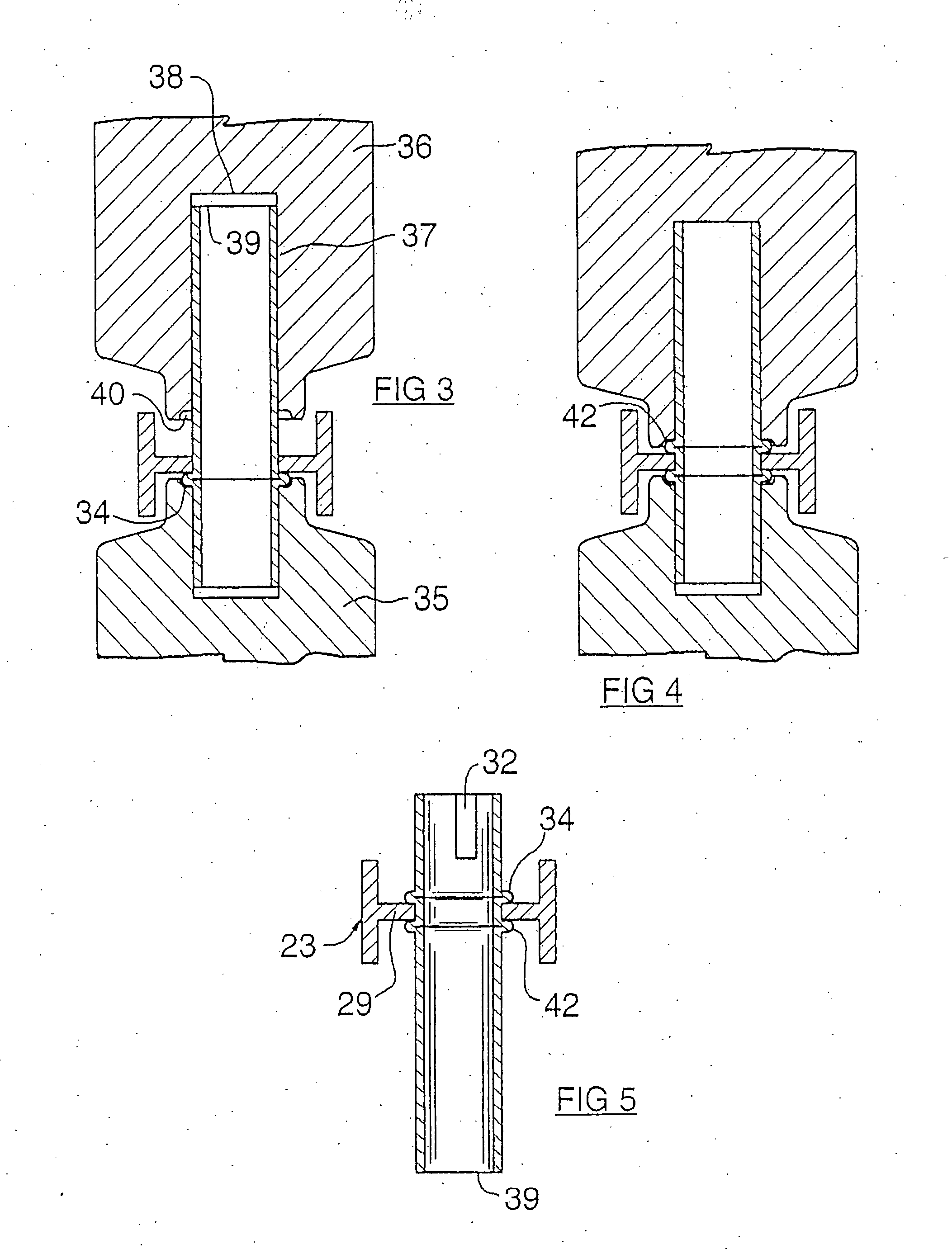
[0020]FIG. 3 is a view of a punch and die set-up, which is used at a stage in the manufacture of one of the headrest supports;

[0021]FIG. 4 is a view corresponding to FIG. 3 of another stage during manufacture;

[0022]FIG. 5 is a cross-section of the headrest mounting support, shown at a later stage;

[0023]FIGS. 6a,6b,6c are cross-sections of a tooling arrangement for forming a metal tube locally into an I-section beam;

[0024]FIGS. 7a,7c are views on the line 7-7 of FIG. 6a, corresponding to the conditions shown in FIGS. 6a and 6c ...


PUM

PropertyMeasurementUnit
Thicknessaaaaaaaaaa
Forceaaaaaaaaaa
Heightaaaaaaaaaa

Abstract

The headrest support tubes are secured to the seat frame member not by the usual welding, but by gripping the web of the member between two rings or lock-beads swaged into the metal of the tube. The first ring is swaged-out by compressing the tube. The tube, with the one ring, is then assembled into a through-hole in the web of the frame member. Then, the second ring is swaged into the metal of the tube, on the other side of the web, and the web lies gripped between the rings. The seat frame member may be an I-section extrusion, or a round tube with localised squeezed-flat areas, flanked by flanges.

Description

[0001] This is a Divisional of patent application Ser. No. 10 / 043,284 filed 14 Jan. 2002, now issued as U.S. Pat. No. ______ (not yet known); [0002] which is a continuation-in-part of patent application Ser. No. 09 / 518,207 filed 3 Mar. 2000, now issued as U.S. Pat. No. 6,338,191; [0003] which is a continuation-in-part of patent application Ser. No. 09 / 064,620 filed 23 Apr. 1998, now issued as U.S. Pat. No. 6,035,516; [0004] which claims priority from GB-97 / 08394 filed 25 Apr. 1997.[0005] This invention relates to the construction of automobile seats, and is directed particularly to the manner of attachment of a headrest to the frame of an automobile seat. BACKGROUND TO THE INVENTION [0006] The headrest on an automobile seat is often made adjustable as to height. One common way in which the headrest is mounted on the seat in a way that permits height adjustment is for the headrest to be provided with two downwardly extending pegs, and the pegs engage sockets secured into the frame of...

Claims


Application Information

Patent Timeline
IPC IPC(8): B21D39/04B21D39/06B60N2/48
CPCB21D39/044B21D39/06B60N2/48B60N2/4802Y10T29/4994Y10T29/53996Y10T29/49925Y10T29/49915Y10T29/4987B60N2/80B60N2/803
Inventor PETERSEN, HORST UDO
Owner BEND ALL AUTOMOTIVE
Why Eureka
Try Eureka