Intra-and/or inter-system interference reducing systems and methods for satellite communications systems

Active Publication Date: 2005-02-17
ATC TECH LLC
View PDF98 Cites 240 Cited by
  • Summary
  • Abstract
  • Description
  • Claims
  • Application Information

AI Technical Summary

Benefits of technology

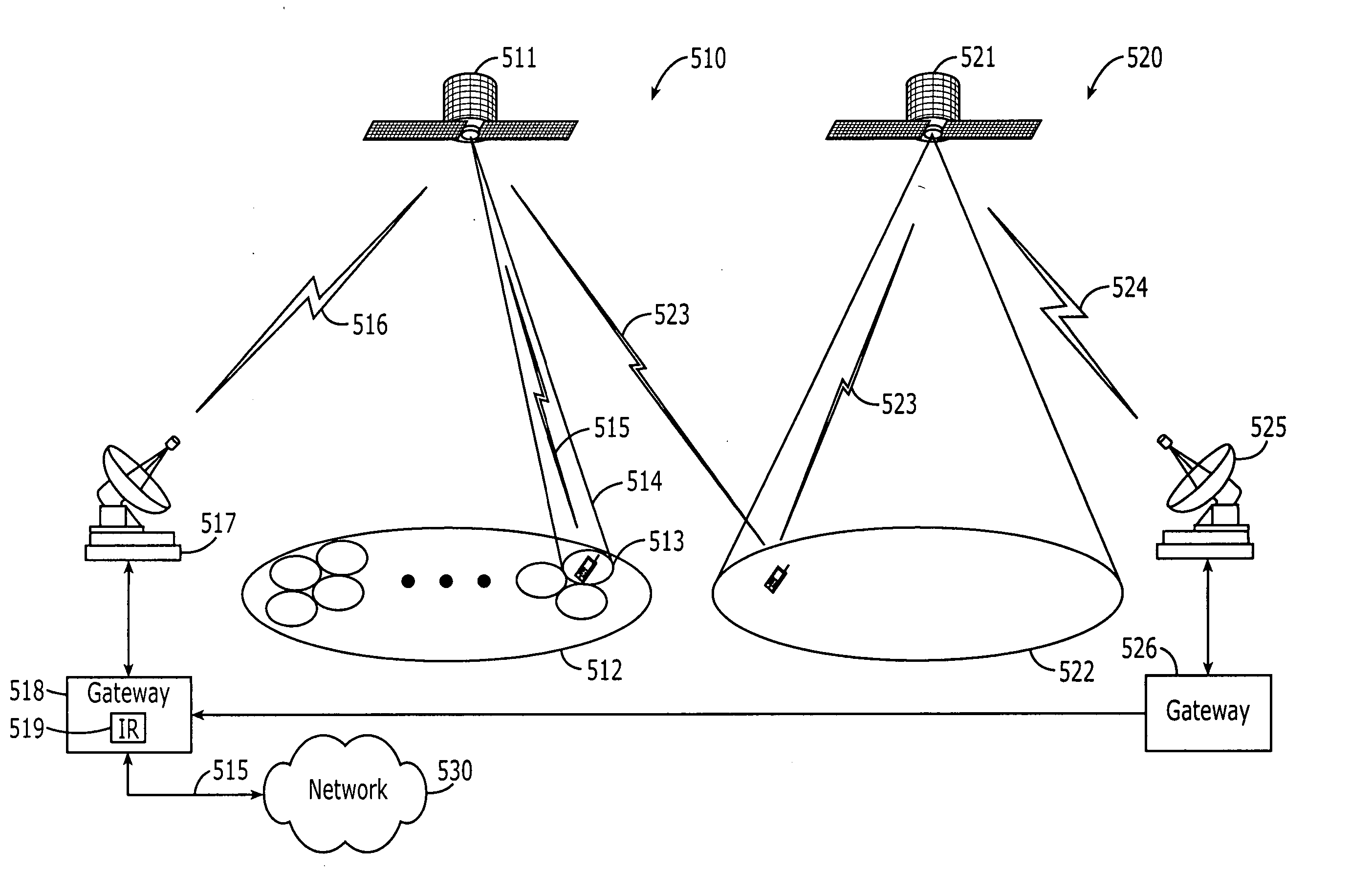
[0010] Some embodiments of the present invention allow two satellite and/or terrestrial communications systems to use the same frequency or frequencies for communications in geographically distinct, overlapping and/or congruent footprints while reducing interference in a given system (inter-system interference) that is caused by the same frequency signal(s) that is (are) used by the other system. In some embodiments, a satellite of a first satellite and/or terrestrial system includes a receive-only ancillary antenna that is configured to receive signals, occupying at least some of the frequencies of the first satellite and/or terrestrial system, from the second satellite and/or terrestrial system footprint. The received signal(s) from the ancillary antenna can be used to reduce interference to the first satellite and/or terrestrial system by the second satellite and/or terrestrial system. In other embodiments, at least some of the signals from the second satellite and/or terrestrial communications system that have occupied and/or are occupying at least some of the frequencies of the first satellite and/or terrestrial communications system are routed by a gateway and/or other component(s) of the first and/or second satellite and/or terrestrial system, before or after regeneration, to a gateway and/or other component(s) of the first satellite and/or terrestrial system. The routed signals may the

Problems solved by technology

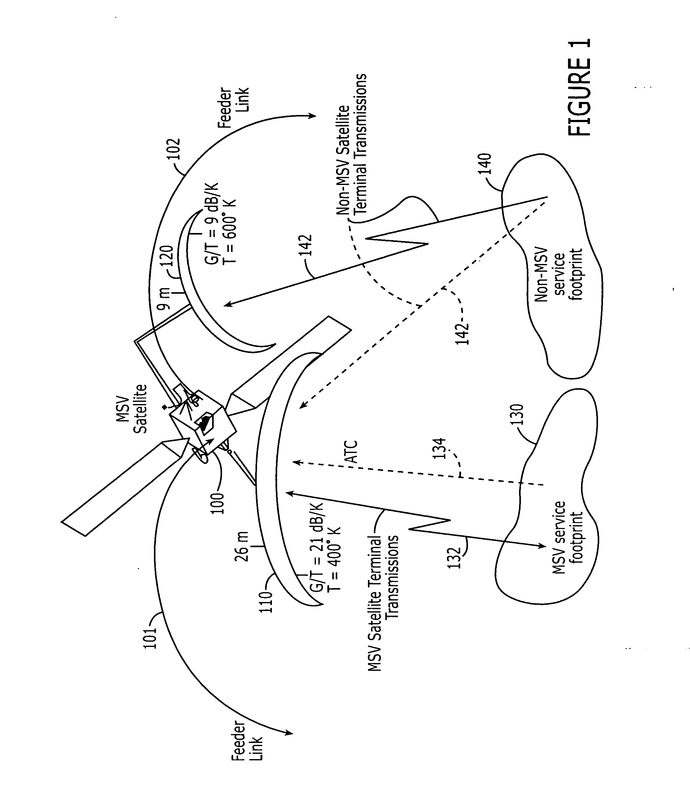
In particular, it is known that it may be difficult for satellite radiotelephone systems to reliably serve densely populated areas, because the satellite signal may be blocked by high-rise structures and/or may not penetrate into buildings.
As a result, the satellite spectrum may be underutilized

Method used


Image

  • Intra-and/or inter-system interference reducing systems and methods for satellite communications systems
  • Intra-and/or inter-system interference reducing systems and methods for satellite communications systems
  • Intra-and/or inter-system interference reducing systems and methods for satellite communications systems

Examples


Embodiment Construction

[0031] Specific exemplary embodiments of the invention now will be described with reference to the accompanying drawings. This invention may, however, be embodied in many different forms and should not be construed as limited to the embodiments set forth herein; rather, these embodiments are provided so that this disclosure will be thorough and complete, and will fully convey the scope of the invention to those skilled in the art. In the drawings, like numbers refer to like elements. It will be understood that when an element is referred to as being “connected” or “coupled” to another element, it can be directly connected or coupled to the other element or intervening elements may be present. Furthermore, “connected” or “coupled” as used herein may include wirelessly connected or coupled. As used herein the term “and / or” includes any and all combinations of one or more of the associated listed items. The symbol “ / ” is also used as a shorthand notation for “and / or”. As used herein th...


PUM


Abstract

A first radio signal is received via a first satellite reception path, for example, an antenna or spot beam, which serves a satellite cell. The received first radio signal includes a desired satellite uplink signal transmitted from a first source using a frequency assigned to the satellite cell and an interfering signal transmitted from at least one second source using the frequency assigned to the satellite cell. A second radio signal is received via a second satellite reception path, for example, via another antenna or spot beam of the system and/or via a satellite antenna beam of another system. The second radio signal includes a measure of the interfering signal. The first and second radio signals are processed to recover the desired satellite uplink signal.

Description

RELATED APPLICATION [0001] The present application claims priority from U.S. Provisional Application Ser. No. 60 / 490,993, entitled Intra- and / or Inter-System Interference Reducing Systems and Methods for Satellite Communications Systems, filed Jul. 30, 2003 and incorporated herein by reference in its entirety.FIELD OF THE INVENTION [0002] This invention relates to wireless communications systems and methods, and more particularly to terrestrial and satellite communications systems and methods. BACKGROUND OF THE INVENTION [0003] Satellite communications systems and methods are widely used for communications. Satellite communications systems and methods generally employ at least one space-based component, such as one or more satellites, that is configured to communicate with at least one radioterminal. [0004] A satellite communications system or method may utilize a single antenna beam covering an entire area served by the system. Alternatively, in “cellular” satellite communications ...

Claims


Application Information

Patent Timeline
IPC IPC(8): H04B7/185
CPCH04B7/1851H04B1/7097
Inventor KARABINIS, PETER D.DUTTA, SANTANUCHURAN, GARY G.ZHENG, DUNMIN
Owner ATC TECH LLC
Why Eureka
Try Eureka