Ophthalmic lens with optimal power profile

a technology of power profile and ophthalmology, applied in the field of ophthalmology, can solve the problems of awkward back and forth between normal and intermediate lenses, inability to tolerate intermediate mono-vision by most individuals, and inability to adjust the power profil

Inactive Publication Date: 2005-02-24
LINDACHER JOSEPH MICHAEL +2
View PDF8 Cites 107 Cited by
  • Summary
  • Abstract
  • Description
  • Claims
  • Application Information

AI Technical Summary

Benefits of technology

[0013] In another aspect, the invention is an ophthalmic lens having an optical axis, a central optical zone and a peripheral optical zone surrounding the central optical zone. The central optical zone has a first diameter and a first corrective power range corresponding to near and intermediate vision. The peripheral optical zone has a second diameter that is greater than the first diameter. The peripheral optical zone is coaxial or nearly coaxial with the central optical zone and provides distance intermediate vision correction.

Problems solved by technology

While there exist contact lenses that provide intermediate correction, having to change back and forth between normal lenses and intermediate lenses is awkward for the user.
Intermediate mono-vision is not well tolerated by most individuals.

Method used


Image

  • Ophthalmic lens with optimal power profile
  • Ophthalmic lens with optimal power profile
  • Ophthalmic lens with optimal power profile

Examples


Embodiment Construction

[0025] As used herein “manifest refraction” means a user's subjective best correction for an eye. The “manifest corrective refractive power” means a refractive power required for achieving a user's subjective best correction for an eye.

[0026] As used herein “negative spherical aberration” in reference to a lens means that the optical power decreases as the value of diameter increases. The amount of spherical aberration depends on the diameter. For a lens having a negative spherical aberration, its optical power at the center is larger than an optical power at any diameter. It should be understood that where a lens having a negative power (e.g., −6 diopters), its optical power at any diameter is more negative than its optical power at the center.

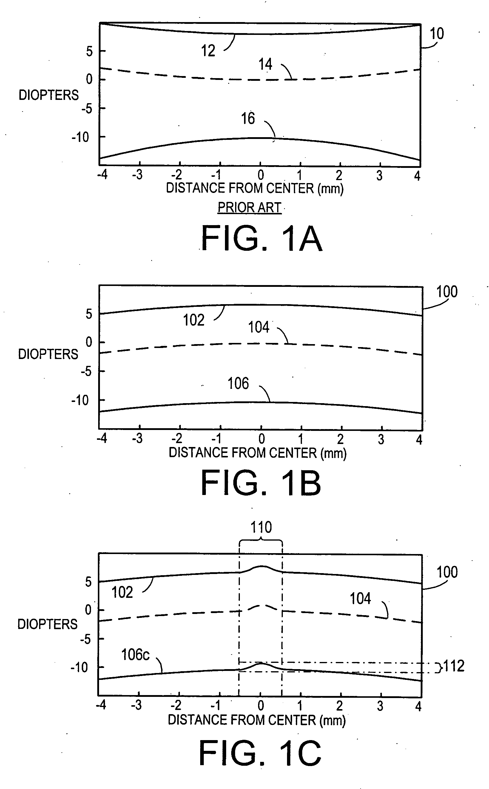
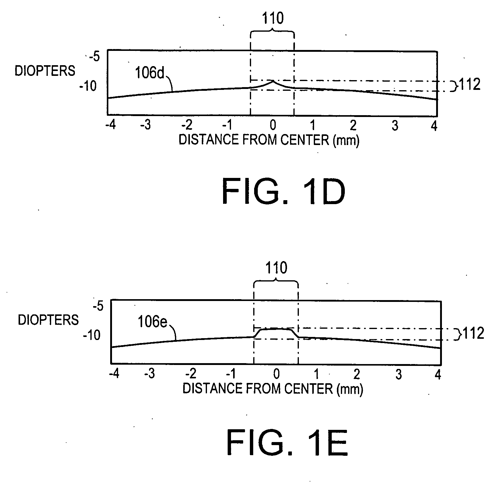
[0027] One embodiment of the invention is a lens that cancels the nominal amount of spherical aberration of the eye, which is approximately 1 diopter at a 6 mm diameter pupil for an adult, regardless of the eye's sphero-cylindrical manifest...


PUM


Abstract

An ophthalmic lens includes an optical zone having a center and a spaced-apart periphery. The optical zone has a first corrective power range in a first region and a second corrective power range in an annular region surrounding the first optical zone. The second corrective power is corrective of spherical aberration of an eye. The optical zone has a power profile that gradually changes from the first corrective power to the second corrective power. A central progressive zone that provides intermediate vision correction may be applied to a central region of the lens. The progressive zone has a diameter that is less than or equal to the diameter of an aperture of a pupil when subjected to bright light.

Description

[0001] This application claims the benefits under 35 USC § 119(e) of U.S. provisional application No. 60 / 496,456, filed Aug. 20, 2003, incorporated by reference in its entirety. This application incorporates by reference co-pending U.S. patent application Ser. No. 10 / 616,378, entitled “Method for Manufacturing a Contact Lens”, filed on Jul. 9, 2003, commonly assigned to the asignee of the present application, the disclosure of which is incorporated herein in its entirety.[0002] The present invention relates to ophthalmic lenses and, more specifically to an ophthalmic lens having an optimal power profile for vision. BACKGROUND OF THE INVENTION [0003] Contact lenses are ophthalmic lenses worn on the anterior cornea that are widely used for correcting many different types of vision deficiencies. These include defects such as near-sightedness (myopia) and far-sightedness (hypermetropia), astigmatism, and defects in near range vision usually associated with aging (presbyopia). A typical ...

Claims


Application Information

Patent Timeline
Patent Type & Authority Applications(United States)
IPC IPC(8): G02C7/04
CPCG02C7/028G02C7/044G02C7/042
Inventor LINDACHER, JOSEPH MICHAELMORGAN, COURTNEY FLEMANDINO, RAFAEL VICTOR
Owner LINDACHER JOSEPH MICHAEL
Why Eureka
Try Eureka