Multifocal lens system for digital cameras

a multi-focal lens and digital camera technology, applied in the field of optical systems, can solve the problems of large camera volume, complicated and difficult construction, and relatively expensive zoom lenses, and achieve the effect of reducing the cost of zooming

Inactive Publication Date: 2005-02-24
ARC DESIGN
View PDF4 Cites 51 Cited by
  • Summary
  • Abstract
  • Description
  • Claims
  • Application Information

AI Technical Summary

Benefits of technology

[0007] A primary object of the present invention is to provide a multifocal lens system for digital cameras comprising a wide-angle lens, a telephoto lens, a parallelogram prism or a pair of triangular prism, and a certain mechanism with which the prism or the prisms can be moved sliding from side to side. The wide-angle lens is placed in front of an image sensor such as CCD or C-MOS aligning its optical axis with the center of the image sensor. The telephoto lens is placed alongside the wide-angle lens. A parallelogram prism or a pair of triangular prisms is placed movably at the rear of those two lenses. When the wide-angle lens is to be used, the parallelogram prism or one of the two triangular prisms is positioned not to cover any part of the sensor, and stay only at the rear of the telephoto lens, so that the wide-angle lens can be focused on the sensor to capture an image. When the telephoto lens is to be used, the parallelogram prism or one of the two triangular prisms moves onto the image sensor to cover its sensing area enabling light from the object to pass therethrough and shutting light through the wide-angle lens, so that the telephoto lens can be focused on the sensor to capture an image.
[0008] Thus the multifocal lens system according to the present invention is so designed as to be capable of changing focal length instantly by moving only the parallelogram prism or the two triangular prisms at the rear of the wide-angle and telephoto lenses from side to side. It is not necessary for the multifocal lens system according to the present invention to rotate both of the wide-angle and telephoto lenses using a turret mechanism that is bulky and occupies much more space, also it is not necessary to attach a bulky conversion lens onto the master lens, and further it is not necessary to insert any auxiliary lenses behind the master lens to change the focal length of the lens system, which is rather complicated in mechanism and yet not capable enough to change the focal length magnification effectively.
[0009] Moreover the multifocal lens system according to the present invention uses the telephoto lens of which the light path is reflected through the parallelogram prism or reflected on the mirror surfaces of the two triangular prisms, and consequently the distance between the wide-angle lens and the focal plane of the sensor and the physical distance between the telephoto and the focal plane of sensor could be almost the same, and the telephoto lens can be placed at the same level as the wide-angle lens preventing the telephoto lens from protruding much higher than the level of wide-angle lens.

Problems solved by technology

The zoom lenses are relatively expensive and constructions are complicated and difficult to be made.
The lens turret system is much easier than zoom lenses in manufacturing, however, longer focal lenses are always protruded and cannot be retracted in to the camera body, and that makes the camera bulky.
One is to be attached to the front of camera lens, of which the focal magnification is very limited due to its size, and it is extremely difficult to obtain a focal magnification of two times. This type of front conversion lenses is too bulky for a DSC, because usually the sizes of DSC lenses are much smaller than analogue camera lenses, and when used in a DSC, the durability of the total lens with a front conversion lens will be in question.
The other is a behind lens type conversion (a rear conversion lens), which is to be inserted behind the master lens to change the focal length of the master lens, but also the ratio of focal magnification is limited, and further more the mechanism to insert the rear conversion lens behind the very small sized DSC master lens is very complicated and not easy to be designed and manufactured.

Method used


Image

  • Multifocal lens system for digital cameras
  • Multifocal lens system for digital cameras
  • Multifocal lens system for digital cameras

Examples


Embodiment Construction

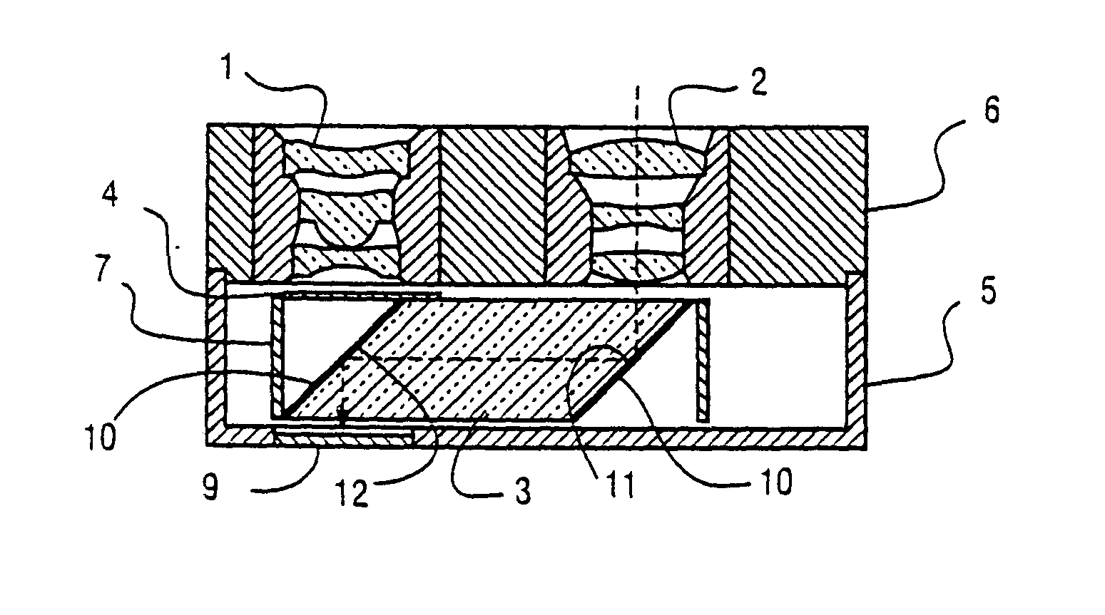
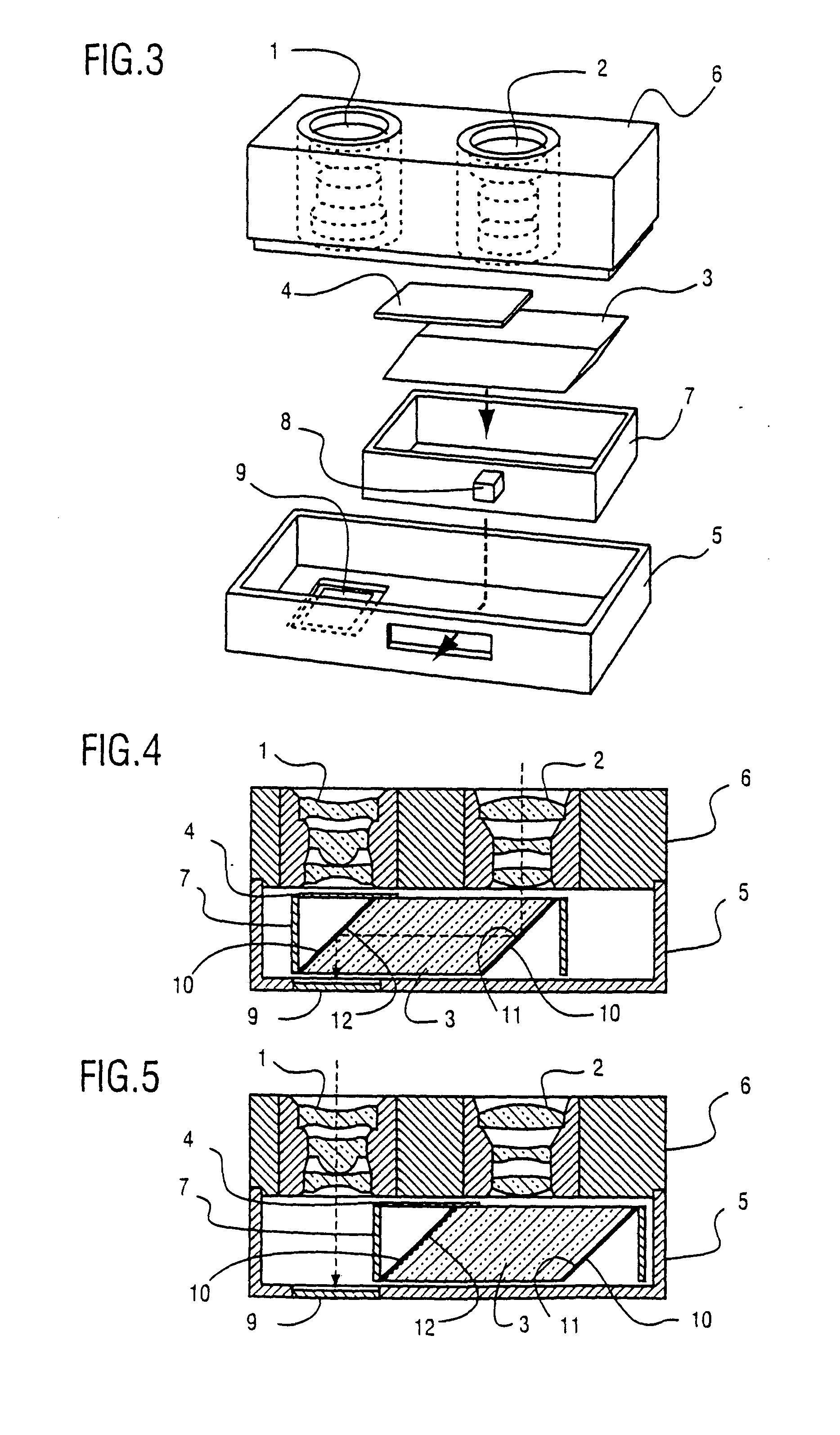
[0018]FIGS. 3, 4&5 show a preferable embodiment of the present invention, namely the multifocal lens system for digital cameras, which comprises a wide-angle lens (1), a telephoto lens (2), a parallelogram prism (a rhombic shaped prism) (3), a shutter blade (4) attached on said prism, a housing (5), a lens holder (6) and a prism holder (7). The wide-angle lens (1) and the telephoto lens (2) are positioned side by side on top of the lens holder (6) as shown by FIGS. 4 & 5. Inside the housing (5), there is the parallelogram prism (3), which is held by the prism holder (7). The prism holder (7) is movable from side to side at the rear of the wide-angle (1) and telephoto (2) lenses sliding inside the housing (5), and the prism holder (7) can be operated by a knob (8) from side to side from the outside of the housing (5). On the prism holder (7) the shutter blade (4) is provided, and when the wide-angle lens (1) is in use as shown by FIG. 5, the shutter blade (4) and the parallelogram pr...


PUM


Abstract

A multifocal lens system to be used for digital cameras for setting any one of a plurality of lenses in a picture taking (image capturing) position comprising a wide-angle lens (shorter focal length lens) mounted in front of an image sensor in a picture taking (image capturing) position, a telephoto lens (longer focal length lens) mounted alongside the wide-angle lens, a parallelogram prism (rhombic prism) or a pair of triangular prisms removably arranged between the two lenses at the rear of them. When the wide-angle lens is to be used, the parallelogram prism or one of the two triangular prisms is to be removed from the rear of wide-angle lens so that the wide-angle lens can be focused on the sensor enabling light to pass therethrough. The telephoto lens is so positioned that it may be focused on the image sensor through the parallelogram prism or being reflected by the triangular prisms enabling light to pass therethrough when a part of the parallelogram prism or one of the two triangular prisms is placed in front of the image sensor to cover the imaging area of the sensor and to shut the light through the wide-angle lens to the sensor. By moving the prism from the rear of each lens, one of the two lenses can be positioned for picture taking (image capturing).

Description

BACKGROUND OF THE INVENTION [0001] 1. Field of the Invention [0002] The present invention relates to an optical system that has a plurality of lenses of two different focal lengths in a digital camera (hereinafter referred to as DSC), and by using a parallelogram prism (rhombic prism) or a pair of triangular prisms those two lenses can be placed in the image capturing position interchangeably. [0003] 2. Background Art [0004] To obtain different focal lengths in a camera, usually zoom lenses, multifocal lens turrets and conversion lenses have been commonly used. The zoom lenses are relatively expensive and constructions are complicated and difficult to be made. The lens turret system is much easier than zoom lenses in manufacturing, however, longer focal lenses are always protruded and cannot be retracted in to the camera body, and that makes the camera bulky. There are two kinds of conversion lens. One is to be attached to the front of camera lens, of which the focal magnification i...

Claims


Application Information

Patent Timeline
Patent Type & Authority Applications(United States)
IPC IPC(8): G02B3/00G02B7/00G02B9/00G02B13/16G03B13/32G03B17/14G03B19/12H04N5/225
CPCH04N5/2254G03B17/14H04N23/55
Inventor OSHIMA, SHIGERUYAMAZAKI, YOSHIO
Owner ARC DESIGN
Why Eureka
Try Eureka