Monitor apparatus

a monitor and monitor body technology, applied in the direction of casings/cabinets/drawers, instruments, casings/cabinets/drawers, etc., can solve the problems of limiting or disabling the pivoting function of the monitor apparatus, user discomfort watching the monitor, inconvenient and complicated to pivot the monitor main body and adjust the angle and height simultaneously

Inactive Publication Date: 2005-02-24
SAMSUNG ELECTRONICS CO LTD
View PDF12 Cites 93 Cited by
  • Summary
  • Abstract
  • Description
  • Claims
  • Application Information

AI Technical Summary

Benefits of technology

[0013] Accordingly, it is an aspect of the present invention to provide a monitor apparatus preventing a corner of a monitor main body from contacting with a base member or a flat surface on which the monitor is located, by controlling a distance between the monitor main body and the base member while the monitor main body is pivoting relative to the base member.

Problems solved by technology

However, if the monitor apparatus is pivoted as described above, a corner of the monitor main body contacts with the base member and the flat surface on which the base member is located causing problems of limiting or disabling the pivoting function of the monitor apparatus because a distance between the monitor main body and the base member or between the monitor main body and the flat surface where the base member is located is not sufficient.
Such problems are obvious in a wide monitor apparatus which is increasing in demand recently.
Another problem is that when the monitor main body is pivoted without having its angle and height adjusted to match with a user's eye level, the user may feel uncomfortable watching the monitor.
Thus, it is inconvenient and complicated to pivot the monitor main body and to adjust its angle and height simultaneously.

Method used


Image

  • Monitor apparatus
  • Monitor apparatus
  • Monitor apparatus

Examples


Embodiment Construction

[0035] Reference will now be made in detail to the embodiments of the present invention, examples of which are illustrated in the accompanying drawings, wherein like reference numerals refer to like elements throughout. The embodiments are described below to explain the present invention by referring to the figures.

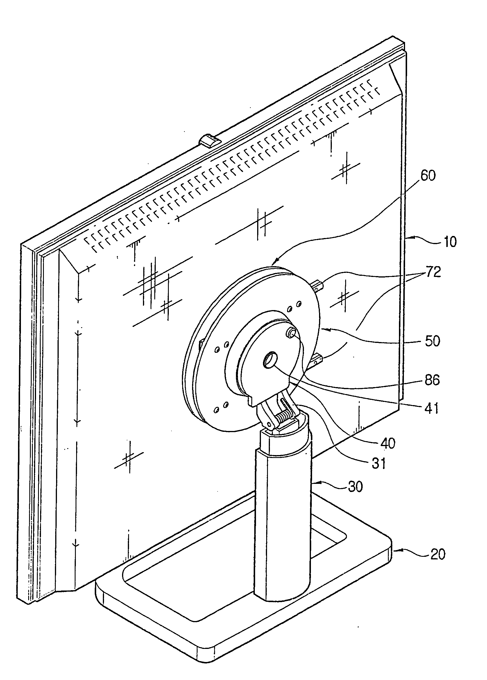
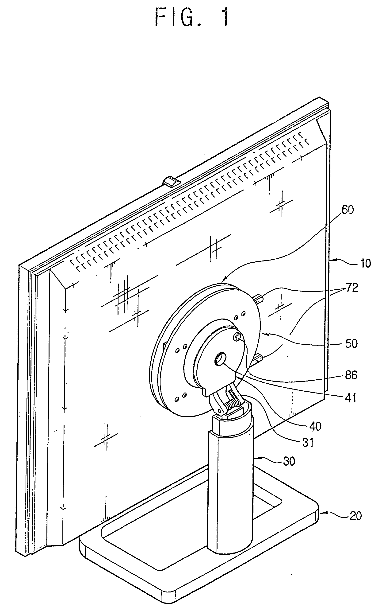
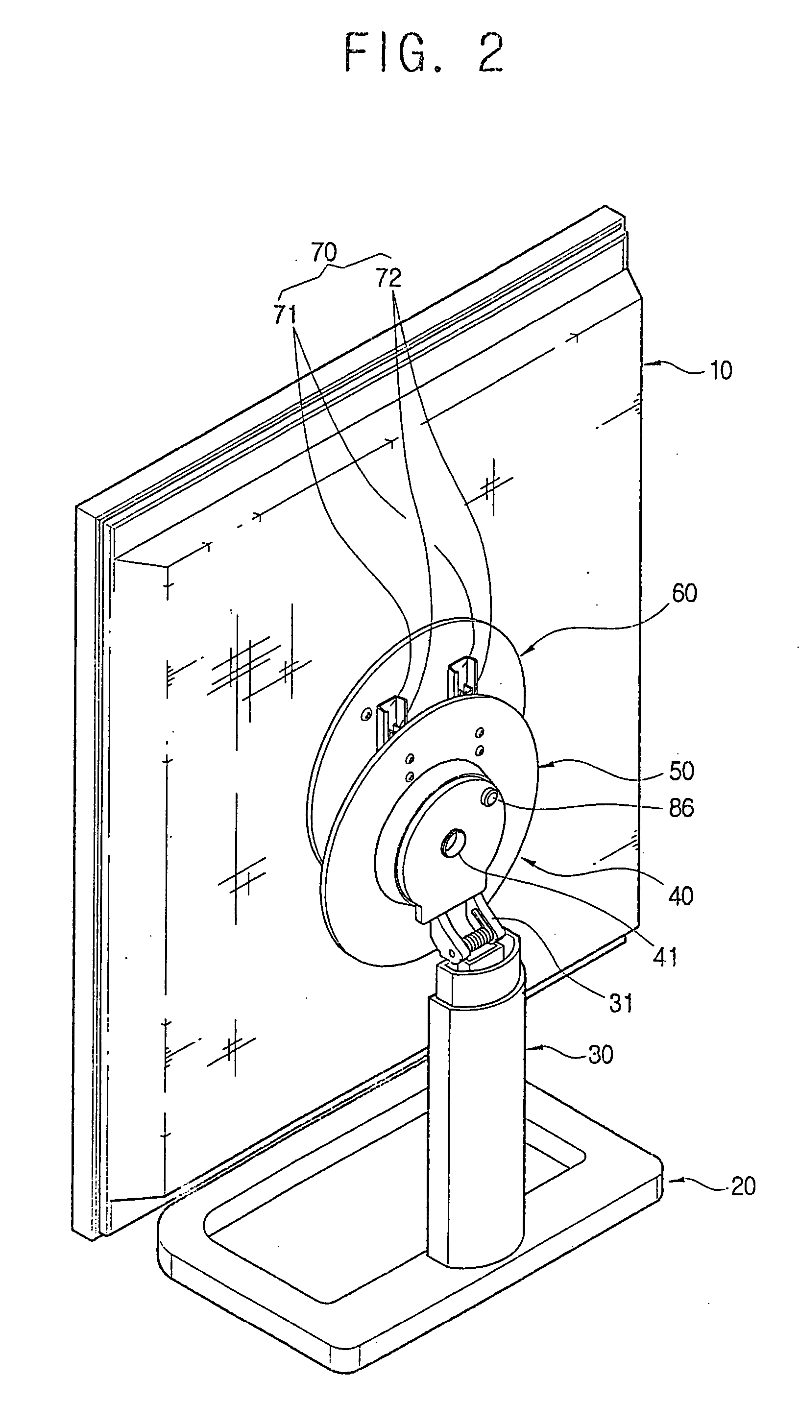
[0036] An example of a monitor apparatus to be described hereafter will be an LCD (Liquid Crystal Display) and a PDP (Plasma Display Panel), wherein a flat image display panel is provided.

[0037] Also, as terminologies to be described in a detailed description of an embodiment of the present invention, a pivoting direction refers to the monitor main body rotating about a clockwise and counterclockwise direction, and a tilting direction refers to the monitor main body rotating about a forward and backward direction relative to a connecting member.

[0038] In FIG. 1 through FIG. 6, the monitor apparatus according to the embodiment of the present invention comprises a monito...


PUM


Abstract

A monitor apparatus includes a monitor main body displaying a picture; a base member supporting the monitor main body; a connecting member combined to the base member, and supporting the monitor main body to be pivoted; a first guide plate having a first side pivotably combined to the connecting member, and a second side to be slidably combined to the monitor main body; a sliding unit provided between the first guide plate and the monitor main body and supporting the first guide plate to be slidable on the monitor main body; and a link unit having a first side combined to a rear side of the monitor main body and a second side combined with the connecting member, so that the monitor main body moves up and down with respect to the base member by sliding on the first guide plate when the first guide plate pivots with respect to the connecting member.

Description

CROSS-REFERENCE TO RELATED APPLICATIONS [0001] This application claims the benefit of Korean Patent Application No. 2003-58029, filed on Aug. 21, 2003, in the Korean Intellectual Property Office, the disclosure of which is incorporated herein by reference. BACKGROUND OF THE INVENTION [0002] 1. Field of the Invention [0003] The present invention relates to a monitor apparatus, and more particularly, a monitor apparatus improved in a pivoting structure of a monitor main body relative to a base member. [0004] 2. Description of the Related Art [0005] A monitor apparatus, in general, comprises a monitor main body, and a base member disposed on a flat surface like a table, to support the monitor main body. [0006] Recently, a monitor main body is produced using an image display panel such as an LCD (Liquid Crystal Display) and a PDP (Plasma Display Panel) which make the monitor main body slim comparable to the size of a screen. [0007] By using such a flat-typed image display panel, the mon...

Claims


Application Information

Patent Timeline
Patent Type & Authority Applications(United States)
IPC IPC(8): F16M11/04F16M11/06F16M11/24G06F1/16G12B9/08G12B9/10H05K5/02H05K7/14H05K7/16H05K7/18
CPCF16M11/04F16M11/045F16M11/046F16M11/06F16M11/2057Y10S248/92F16M11/28G06F1/1601G06F2200/1612Y10S248/917F16M11/24G06F1/16
Inventor JANG, SE-KI
Owner SAMSUNG ELECTRONICS CO LTD
Why Eureka
Try Eureka