Screw-type extruding machine comprising mixing and kneading disks

a screw-type extruder and disk technology, which is applied in the direction of mixing/kneading with horizontally mounted tools, clay mixing apparatus, rotary stirring mixers, etc., can solve the problems of affecting the efficiency of the whole drive train, and achieve the effect of at least reducing vibration stress

Inactive Publication Date: 2005-02-24
COPERION
View PDF7 Cites 32 Cited by
  • Summary
  • Abstract
  • Description
  • Claims
  • Application Information

AI Technical Summary

Benefits of technology

[0006] It is an object of the invention to improve the screw-type extruding machine in such a way that vibratory problems are at least reduced.

Problems solved by technology

As a result, considerable vibratory stresses can occur in the entire drive train in the case of resonance.

Method used


Image

  • Screw-type extruding machine comprising mixing and kneading disks
  • Screw-type extruding machine comprising mixing and kneading disks
  • Screw-type extruding machine comprising mixing and kneading disks

Examples


Embodiment Construction

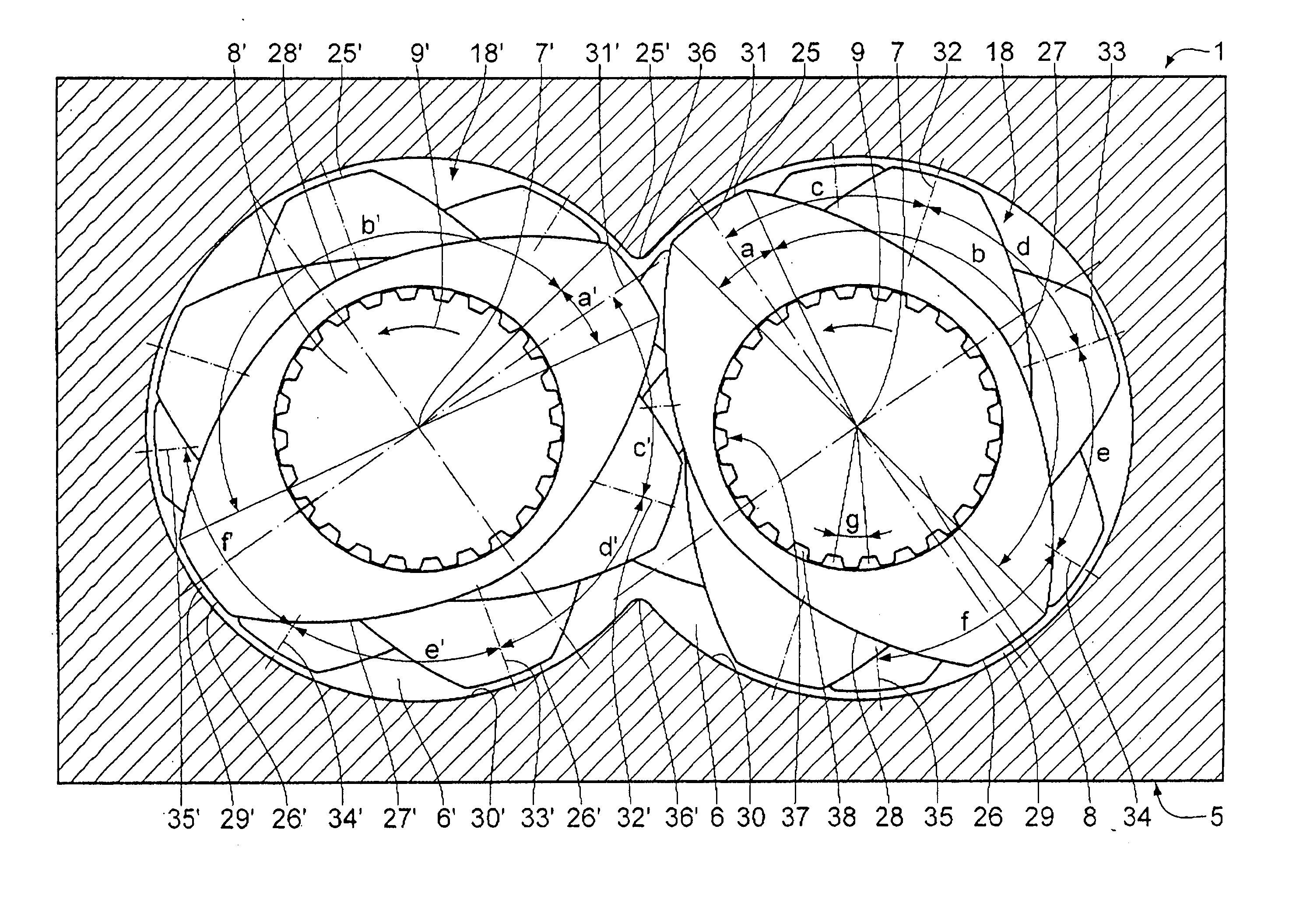
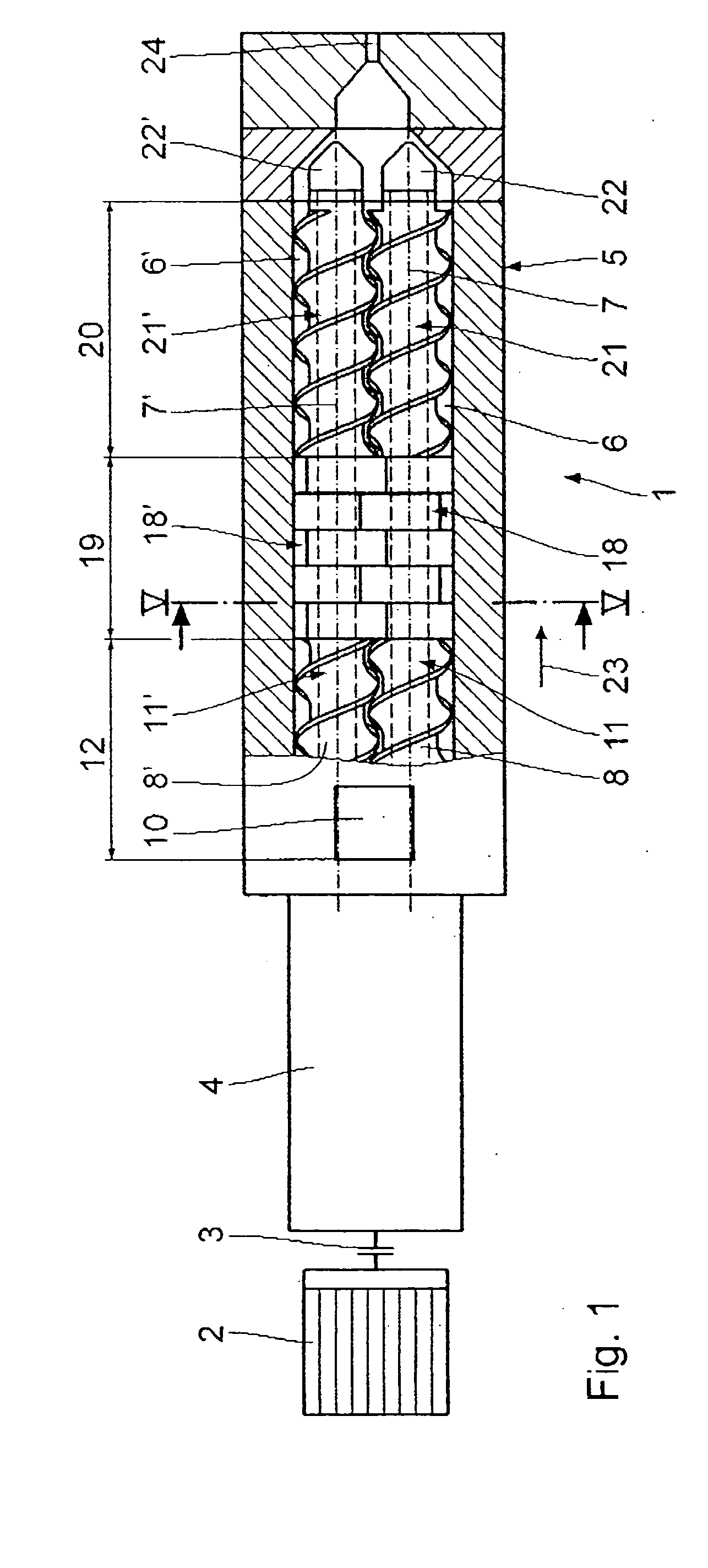
[0016] The twin-screw extruder 1 seen in the drawing is driven by a motor 2 via a coupling 3 and a subsequent transmission 4. The casing 5 of the screw-type extruding machine 1 includes two casing bores 6, 6′ which intersect in the form of a horizontal figure eight, having parallel axes 7, 7′. Screw shafts 8, 8′ are disposed in the bores 6, 6′, the axes of which coincide with the axes 7, 7′. The screw shafts 8, 8′ are driven by way of the transmission 4 in the same direction of rotation 9, 9′.

[0017] At its end in vicinity to the transmission 4, the casing 5 comprises a feed hopper 10, through which to supply material that is to be treated. Subsequently, screws 11, 11′ are mounted on the screw shafts 8, 8′, constituting a feed zone 12.

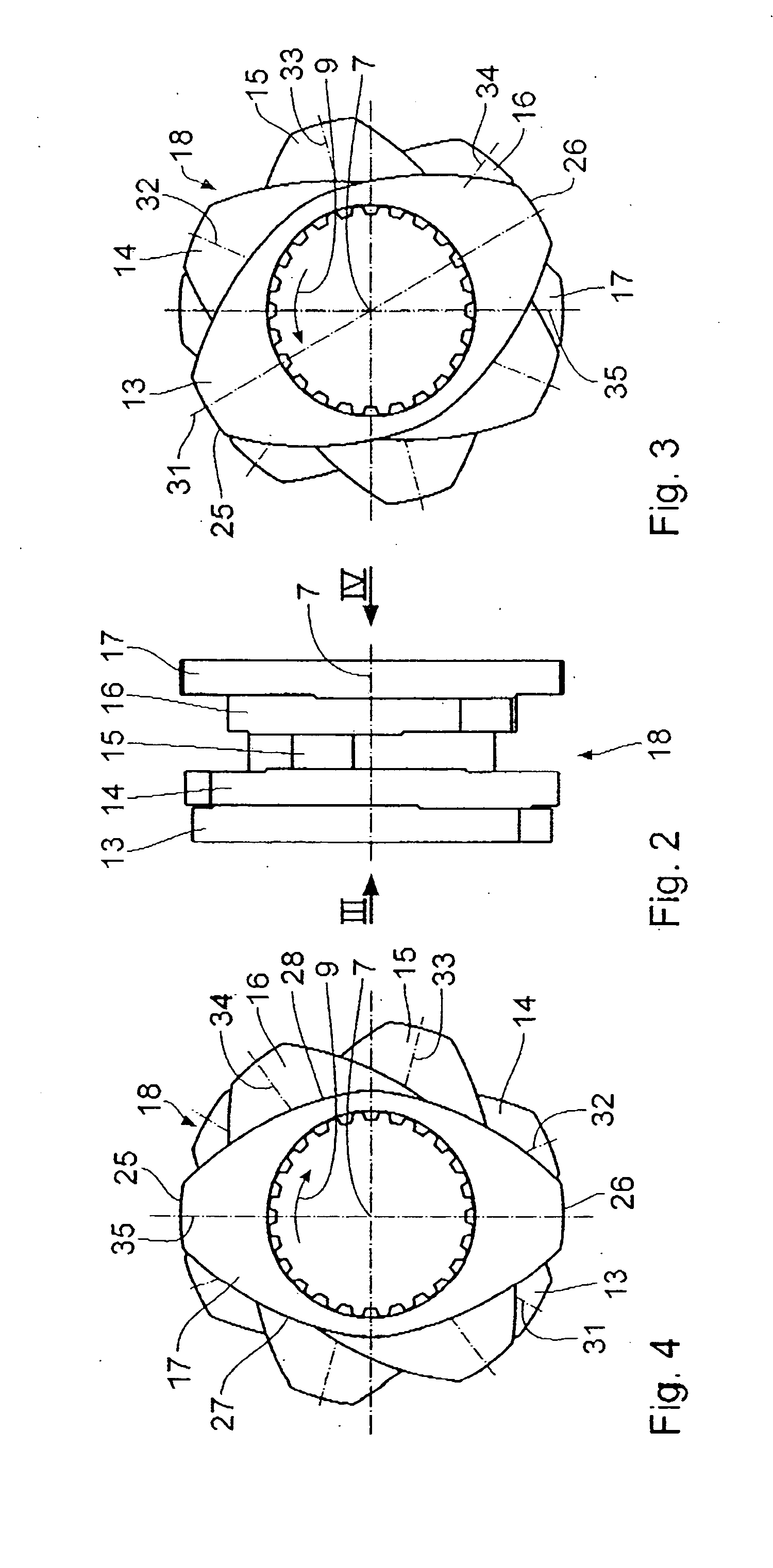
[0018] Subsequently, mixing and kneading disks 13, 13′, 14, 14′, 15, 15′, 16, 16′ and 17, 17′ are non-rotatably mounted on the screw shafts 8, 8′; they are integrally embodied as kneading blocks 18, 18′ in the exemplary embodiment shown. A mixing and ...


PUM

PropertyMeasurementUnit
angle of crestaaaaaaaaaa
angleaaaaaaaaaa

Abstract

A screw-type extruding machine comprises at least two casing bores with screw shafts disposed therein, on which several successive mixing and kneading disks are mounted, interengaging in pairs. Successive mixing and kneading disks make an angle of crest misalignment which is not integrally contained in 360°.

Description

BACKGROUND OF THE INVENTION [0001] 1. Field of the Invention [0002] The invention relates to a screw-type extruding machine comprising at least two parallel, intersecting casing bores; rotarily drivable screw shafts which are disposed in the casing bores; and several mixing and kneading disks which are successively disposed on the screw shafts and interengage in pairs, having at least one crest and at least one flank. [0003] 2. Background Art [0004] Screw-type extruding machines of the generic type which comprise mixing and kneading disks of the generic type have been known to a wide extent, for example from U.S. Pat. No. 6,048,088, U.S. Pat. No. 4,824,256 and EP 1 121 238 B1. In these known screw-type extruding machines, several mixing and kneading disks are successively disposed on a screw shaft, combining to constitute a kneading block. These kneading blocks are designed such that the angle of crest misalignment made by neighboring kneading disks is integrally contained in 360°. ...

Claims


Application Information

Patent Timeline
Patent Type & Authority Applications(United States)
IPC IPC(8): B29C48/57B29B7/42B29B7/48B29C48/03B29C48/06B29C48/54B29C48/67
CPCB29C47/0009B29C47/0016B29C47/0801B29C47/6056B29C47/402B29C47/6031B29C47/0861B29C48/03B29C48/06B29C48/252B29C48/2517B29C48/402B29C48/54B29C48/57B29B7/489B29B7/483
Inventor HERTER, RAINER
Owner COPERION
Why Eureka
Try Eureka