Device and method for detachably connecting abutting structural parts and tie member for use to form said device

a technology of abutting structural parts and ties, which is applied in the direction of furniture joining, rod connection, ropes and cables for vehicles/pulleys, etc., can solve the problems of damage to the assembled piece of furniture, inability to firmly maintain the relationship between the two furniture parts, and the assembler's considerable time and labor. , to achieve the effect of reducing time and labor

Inactive Publication Date: 2005-02-24
TITUS D O O DEKANI
View PDF14 Cites 60 Cited by
  • Summary
  • Abstract
  • Description
  • Claims
  • Application Information

AI Technical Summary

Benefits of technology

[0011] The technical problem underlying the present invention is that of providing a connecting device for detachably connecting two abutting structural parts and in particular of flat furniture parts, such as panels and the like, which allows on the one hand...

Problems solved by technology

Although these connecting devices allow to achieve a traction action adapted to firmly maintain the two furniture parts in abutting relationship even when the assembled piece of furniture is transported or undergoes vibration, the required screwing of the pin members into the respective furniture part involves a considerable time and labor for the assembler which are nowadays hardly accepted by the market.
Although these known connecting devices allow to substantiall...

Method used


Image

  • Device and method for detachably connecting abutting structural parts and tie member for use to form said device
  • Device and method for detachably connecting abutting structural parts and tie member for use to form said device
  • Device and method for detachably connecting abutting structural parts and tie member for use to form said device

Examples


Embodiment Construction

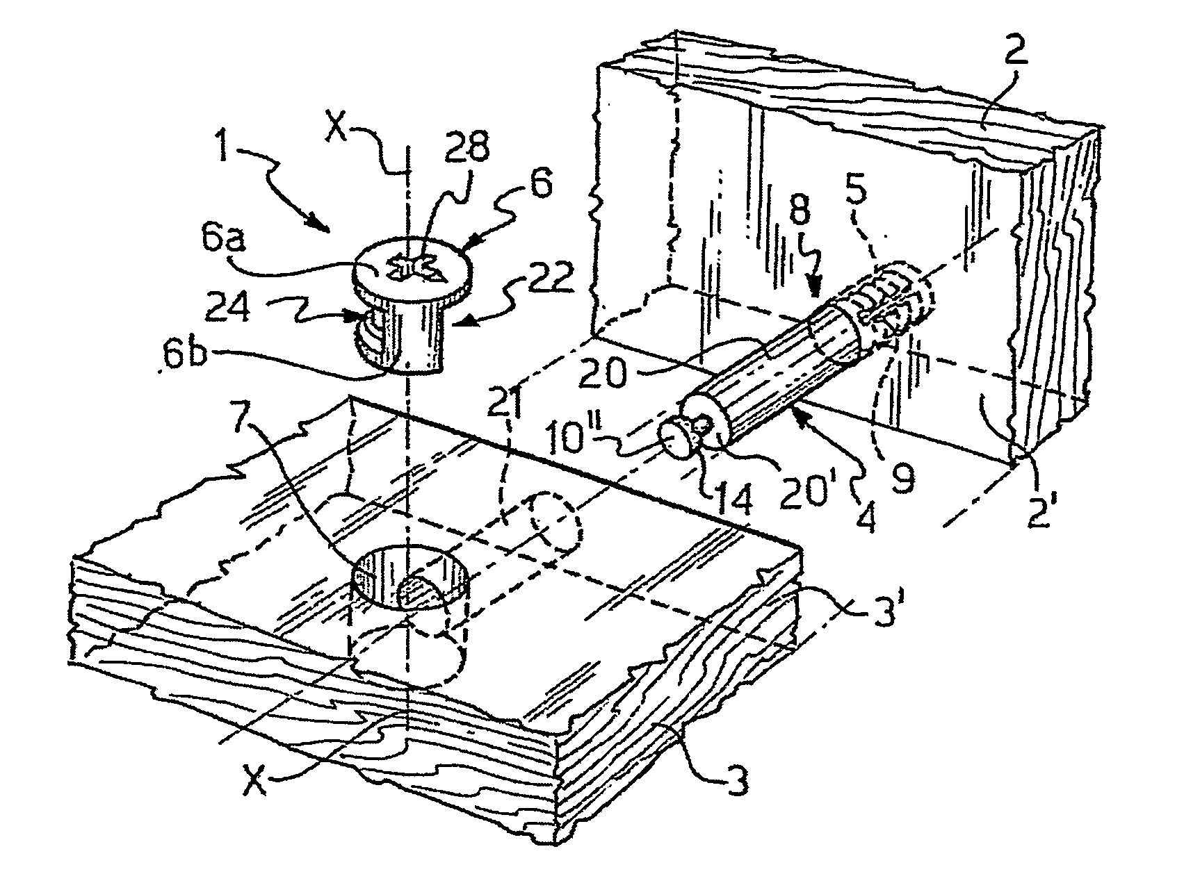
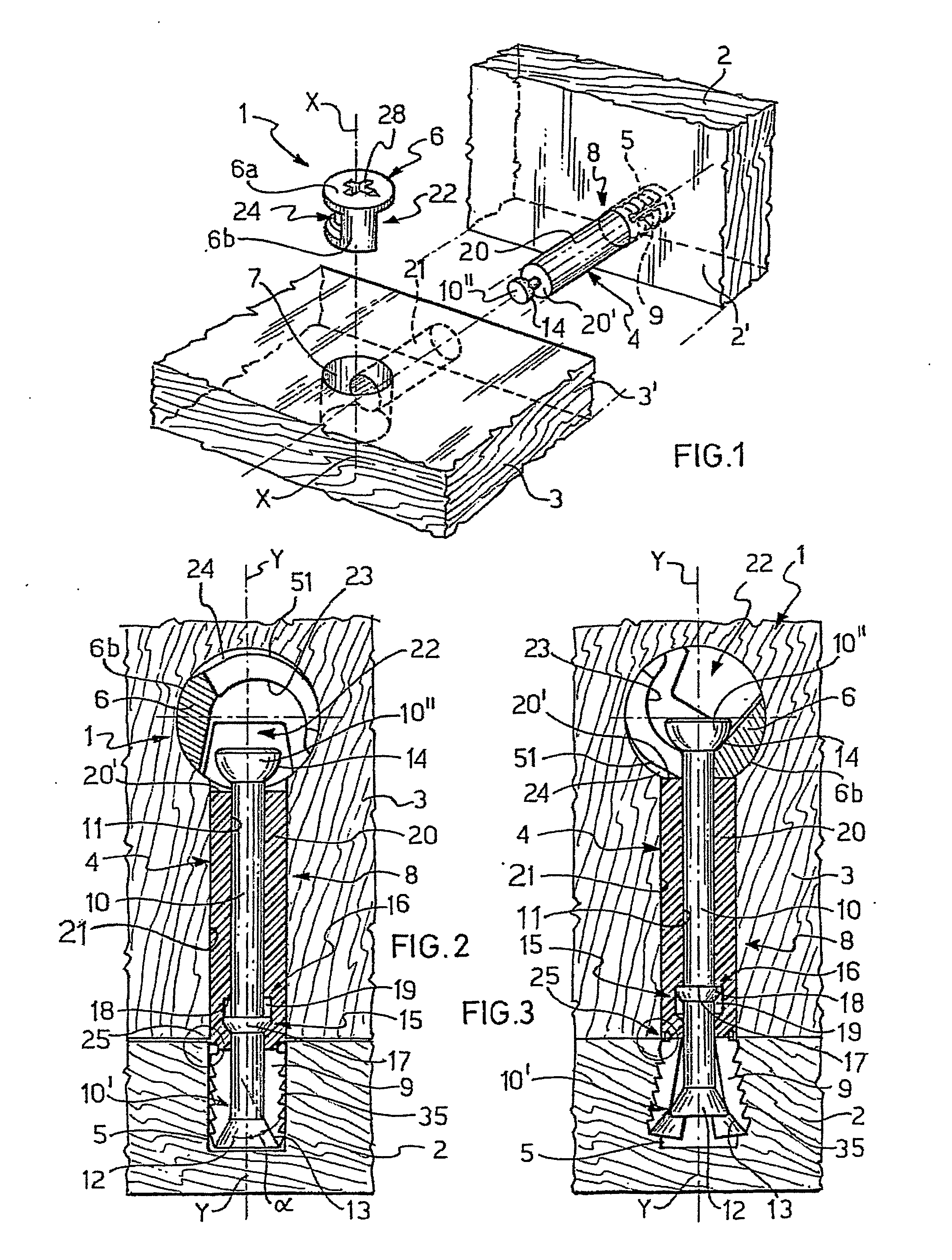
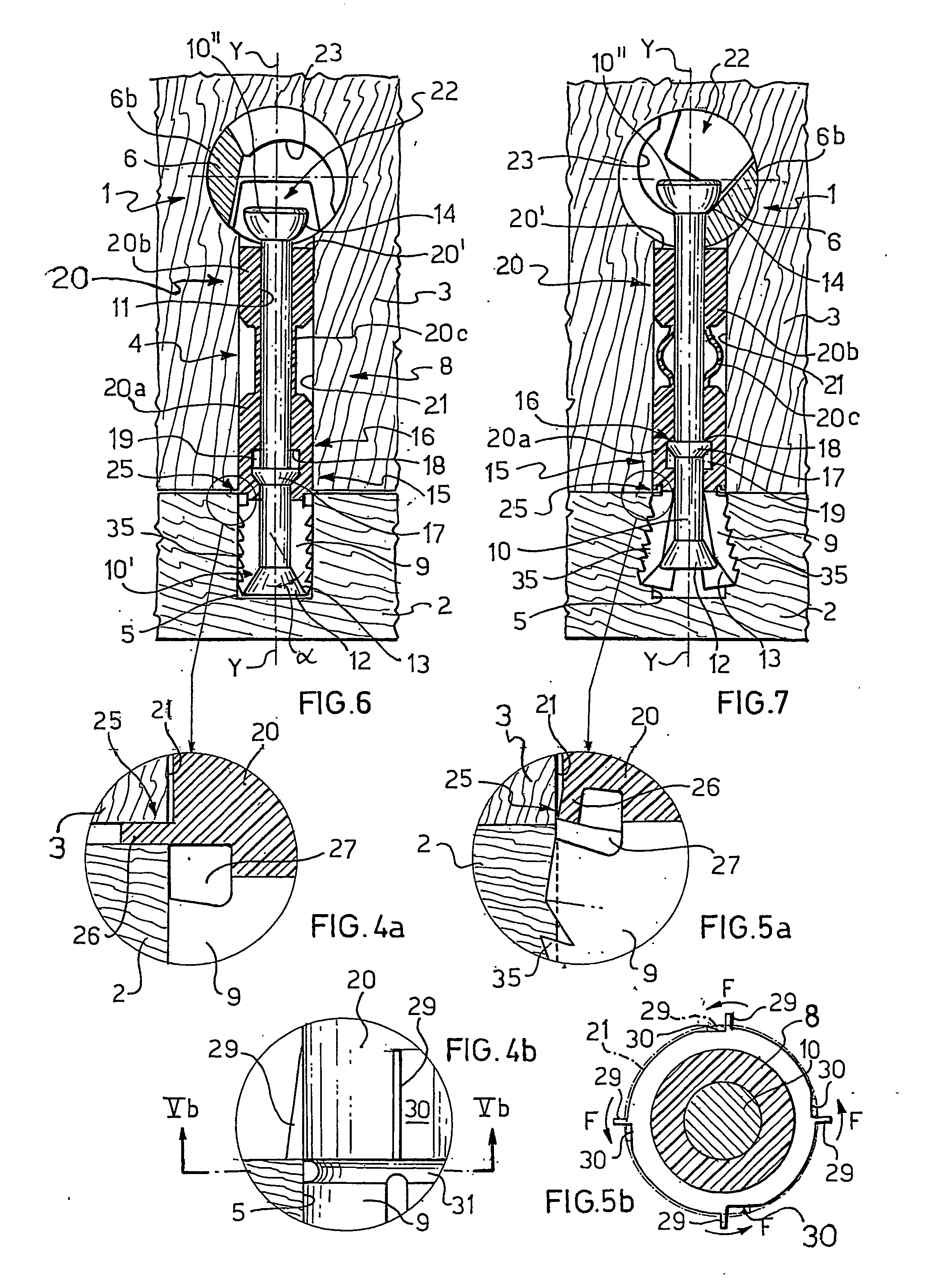
[0123] With reference to FIGS. 1-3, 4a and 5a, a first embodiment of a connecting device according to the invention is generally indicated at 1.

[0124] The connecting device 1 allows to detachably connect two abutting structural parts 2, 3 for example two flat furniture panels which, for the sake of simplicity, have in each case only been shown in part.

[0125] As is customary in this field, the panels 2, 3 are to be connected together in such a manner that they extend at a right angle to each other and the panel 2 has its front surface 2′ resting against the side surface 3′ of the panel 3.

[0126] In this connection, however, it is to be understood that the connecting device 1 of the invention also allows to detachably connect two abutting structural parts inclined at an angle different from 90° provided that the cooperating parts of the device 1 and of the bores formed in the panels 2, 3 and designed to house the same, which will be illustrated in the following, are suitably oriente...


PUM

PropertyMeasurementUnit
Angleaaaaaaaaaa
Thicknessaaaaaaaaaa
Distanceaaaaaaaaaa

Abstract

A device (1) for detachably connecting two abutting structural parts (2, 3) comprises a tie member (4), adapted to be at least partially inserted in a recess (5) formed in a first (2) of the structural parts (2, 3), and a locking element (6) operable to be disposed in a second (3) of the structural parts (2, 3) and to cooperate with an engagement surface (14, 45) of a rod member (10), slidably housed in a body (8) of the tie member (4), to pull the same towards the second structural part (3). The body (8) is provided with a first, expandable, portion (9) adapted to frictionally engage the recess (5) and with an engaging zone (13) cooperating with an expander region (12) of the rod member (10) operable to expand the first, expandable, portion (9) of the body (8) upon displacement of the rod member (10) relative to the same. The rod member (10) is provided with a traction portion (15) radially outwardly extending therefrom and adapted to cooperate with abutment means (16) radially formed in the body (8) of the tie member (4) at a predetermined axial distance from the engaging zone (13) to effect a substantially simultaneous displacement towards the second structural part (3) of the first, expandable, portion (9) of the body (8) of the tie member (4) and of the first structural part (2) in frictional engagement therewith.

Description

BACKGROUND OF THE INVENTION [0001] The present invention generally relates to a connecting device and method for detachably connecting two abutting structural parts. [0002] More particularly, the present invention relates to a connecting device and method for detachably connecting flat structural parts, such as panels and the like, used to manufacture pieces of furniture, as well as to a tie member for use in forming such a device and to mounting kits for knock-down furniture parts comprising said connecting device and tie member. PRIOR ART [0003] In various fields of technology and particularly in the field of furniture assembly, the need often arises of detachably connecting together abutting structural parts such as for example flat furniture parts, such as panels and the like, which are perpendicular to one another (for example the side walls, bottom, top and rear wall of a locker). [0004] To this end, use is largely made of devices which permit a quick, detachable connection of...

Claims


Application Information

Patent Timeline
IPC IPC(8): F16BF16B12/00F16B12/20
CPCF16B12/2009F16B12/2036Y10T403/76Y10T403/4602Y10T29/49874Y10T29/49947
Inventor MIGLI, CARLO
Owner TITUS D O O DEKANI
Why Eureka
Try Eureka