Driving simulator

Inactive Publication Date: 2005-02-24
DAIMLER AG
View PDF16 Cites 58 Cited by
  • Summary
  • Abstract
  • Description
  • Claims
  • Application Information

AI Technical Summary

Benefits of technology

[0028] Alternatively, movement excitation of the gantry bridge can be performed by two electric linear drives which are arranged at the two transverse ends of the gantry bridge. In comparison with belt traction drives, this solution has the advantage of a more compact design since the runners are arranged directly at the ends of the gantry bridge and the stationary elements can be integrated in the rails. Furthermore, when electric linear drives are used, in contrast to belt traction drives, the risk of uncoordinated mechanical excitations of oscillations of the system is largely prevented. Since electric linear drives do not require any intermediate transmission, they are also particularly low in friction. In order to orient the gantry bridge precisely, the two electric linear drives must be actuated synchronously.
[0029] By virtue of synchronous control of the two drive motors which act on the ends of the gantry bridge, as described above, it is possible largely to prevent twisting of the gantry bridge about the vertical axis during normal operation. However, in the event of a fault, considerable twisting may occur. For this reason it is expedient to provide a mechanism which can be used to compensate for twisting of the gantry bridge and to avoid damage to the gantry bridge due to irreversible warping. For this purpose, one end of the gantry bridge is mounted in a rotatable fashion with respect to the drive element which acts on that end, while the connection of the other end of the gantry bridge to the drive element which acts at this point is made by means of a rotary connection which is linearly displaceable to a limited degree in the Y direction.
[0030] In order to displace and accelerate the base unit in the Y direction in a controlled fashion, a second linear displacement device, preferably formed by an electric linear direct drive, is provided on the gantry bridge. In order to avoid twisting and

Problems solved by technology

Such a driving simulation system is thus restricted to testing the ride-related properties of the vehicle, for example the impression when driving on bumpy roads, when driving over kerbs etc.
The lower end of the achievable frequency spectrum is limited in these devices directly by the maximum available displacement distances of the driving simulator.
Although, as described in German patent document DE 28 42 409 A1, it is possible to use what are referred to as washout algorithms to simulate relatively long-lasting horizontal accelerations by means of a rotary movement of the vehicle cabin, handling-related maneuvers in the frequency range below approximately 0.7 Hz are only represented in a very unsatisfactory fashion by such methods.
While the NADS permits, to a certain degree and in selected excitation directions, both handling-related and ride-re

Method used


Image

  • Driving simulator
  • Driving simulator
  • Driving simulator

Examples


Example

DETAILED DESCRIPTION OF THE DRAWINGS

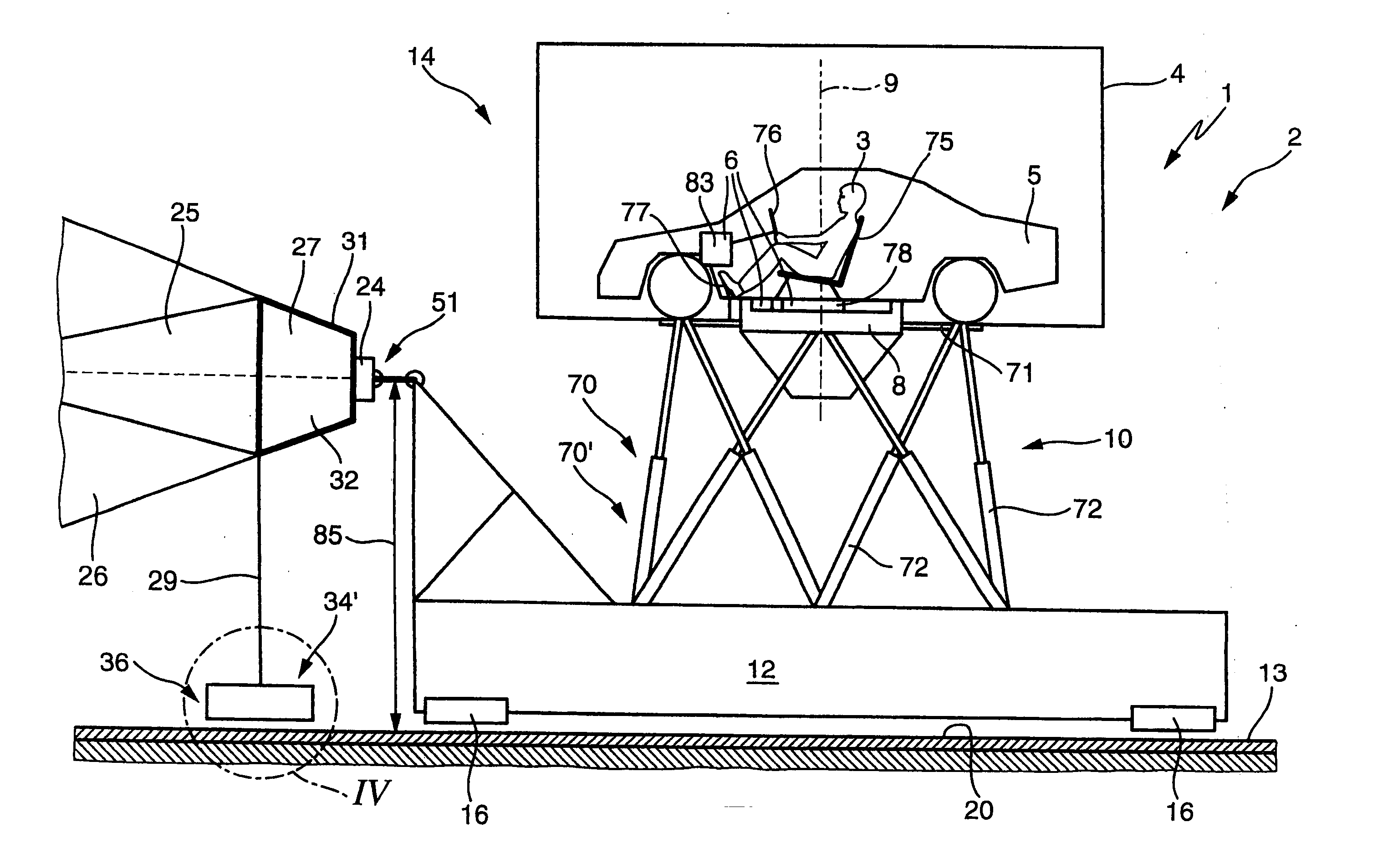
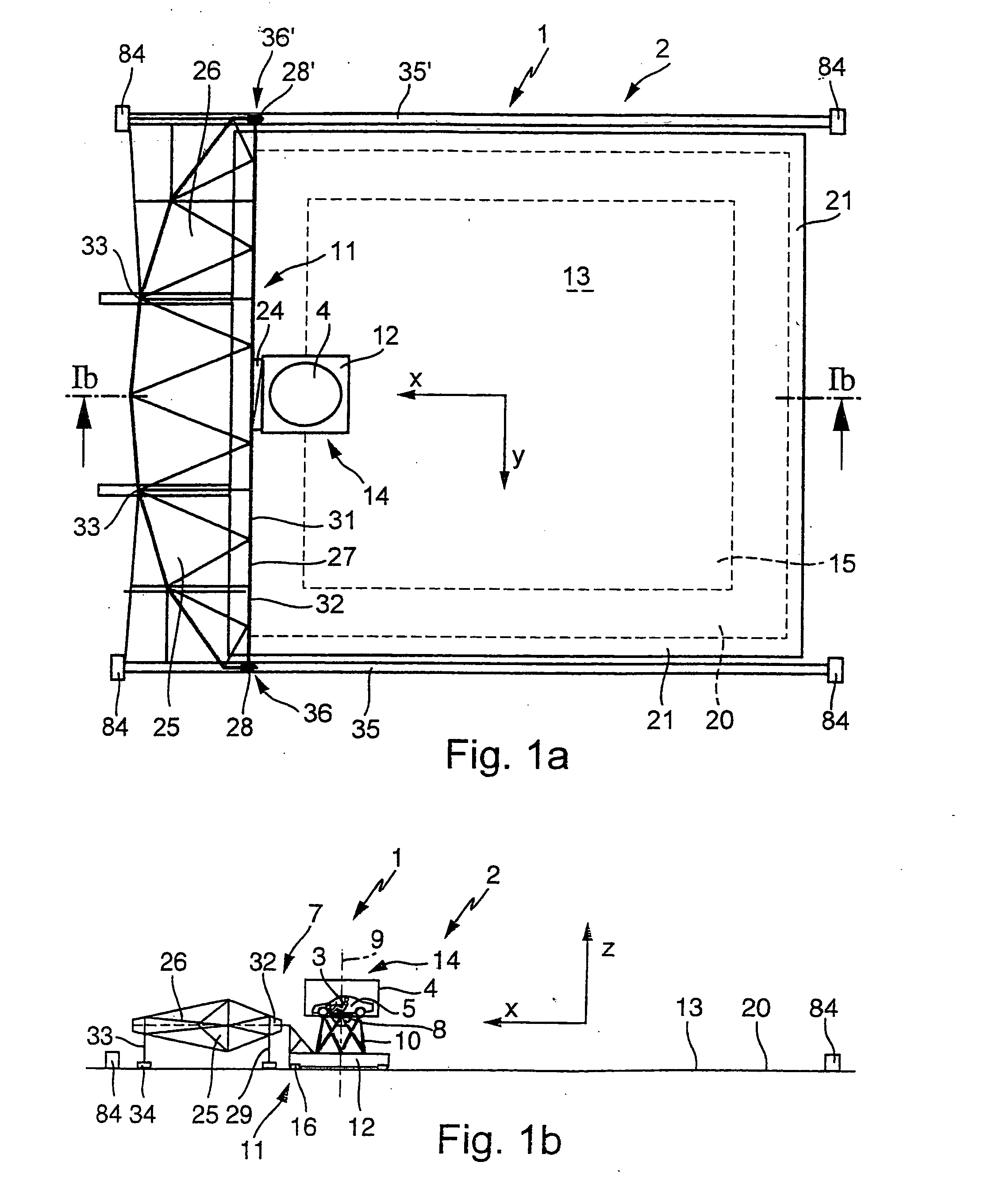
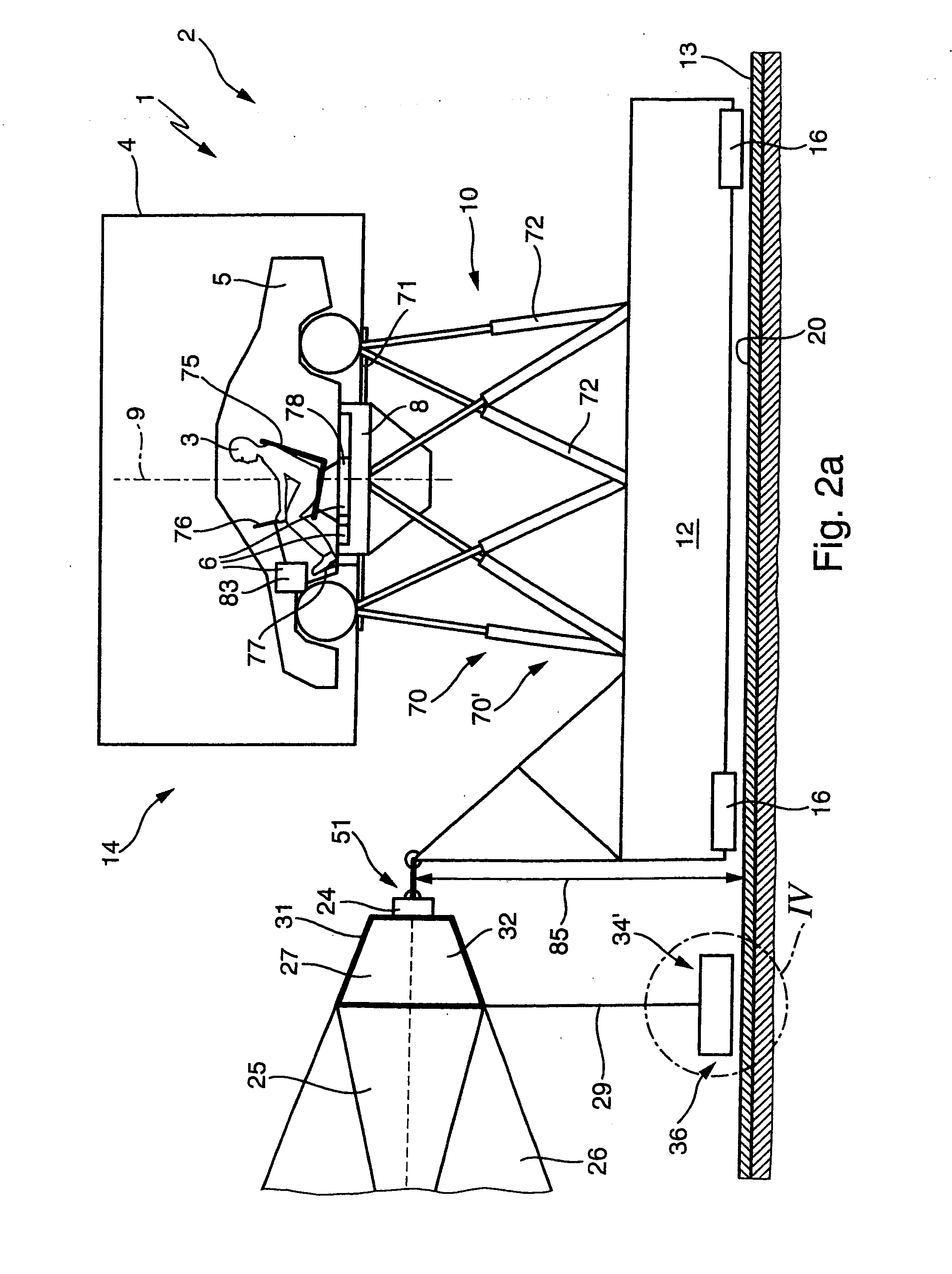
[0056]FIGS. 1a and 1b show a schematic plan view (FIG. 1a), and a side view (FIG. 1b) of a movement system 1 for a driving simulator 2 for producing sensations of movement on a test person 3. The movement system 1 comprises a cabin 5 which is surrounded by an enclosure 4 and has a ride actuating system 6 (described in more detail below). The cabin 5 is fixedly arranged on a manipulator 7, which itself comprises the following components: [0057] a rotary plate 8 for the controlled rotational movement of the cabin 5 about its vertical axis 9, [0058] a six-axle movement unit 10 for moving the assembly composed of the rotary plate 8 and cabin 5 in all six degrees of freedom (three translatory degrees of freedom and three rotational degrees of freedom), [0059] a horizontal displacement device 11 for the controlled displacement and acceleration of the assembly composed of the six-axle movement unit 10, rotary plate 8 and cabin 5 along the two horizontal...


PUM


Abstract

A cascaded overall actuating system for a vehicle motion simulator is divided into an actuating system for small, high-frequency movements and an actuating system for large, low-frequency movements. A manipulator for implementing the low-frequency excitations is itself composed as a cascaded system of a rotary plate, a six-axle movement unit and a horizontal displacement device. To simulate movements which are as low in frequency as possible, the horizontal displacement device spans, as the actuator stage which is arranged at the lowest point in the cascade, a large movement area of 40 m×40 m. The six-axle movement unit with rotary plate and high-frequency actuating system is mounted on a carrier carriage which is supported in a freely displaceable fashion on a planar base surface bounded by the displacement paths of the horizontal displacement device and is pulled and/or pushed with respect to this base surface by means of the horizontal displacement device.

Description

BACKGROUND AND SUMMARY OF THE INVENTION [0001] This application claims the priority of German patent document DE 101 50 382.2, filed Oct. 11, 2001 (PCT International Application No. PCT / EP02 / 09301, filed Aug. 21, 2002), the disclosure of which is expressly incorporated by reference herein. [0002] The invention relates to a movement system for producing motion sensations on test persons. [0003] In the field of motor vehicle construction there is great interest in the continued reduction of development times and costs. As a result, there is also a need to specify design margins in early development stages and to determine physical limits in order to be able to shorten the subsequent development phases and eliminate iteration loops. For this reason, information on the expected driving comfort (ride properties) and the driving behavior (handling properties) of a vehicle design must be available at a very early development stage in order to avoid development loops in the following costly...

Claims


Application Information

Patent Timeline
IPC IPC(8): G01M17/007G09B9/04
CPCG09B9/04
Inventor AMMON, DIETERBOETTIGER, FRIEDRICHDUPLITZER, ENNOFAUL, RUEDIGERGOETZ, JOCHENHERMLE, MARKUSHOFFMEYER, FRIEDRICHLAESSING, MARCPETERSEN, UWERUSSOW, JOERGSCHULZ, THOMAS
Owner DAIMLER AG
Why Eureka
Try Eureka